144
Error Messages/Warning Messages/Condition Messages
Appendix
Warning Messages
When one of the problems described below is detected, a
warning mark is displayed in the upper left corner of the
display. Operation can continue even when the mark is
flashing.
If you press the SFT button (see page 21) and the DIAG
button (see page 19) when the mark is flashing, an
information display appears, showing a warning message.
The warning messages can be viewed in any menu except
the CUE or SET UP menu.
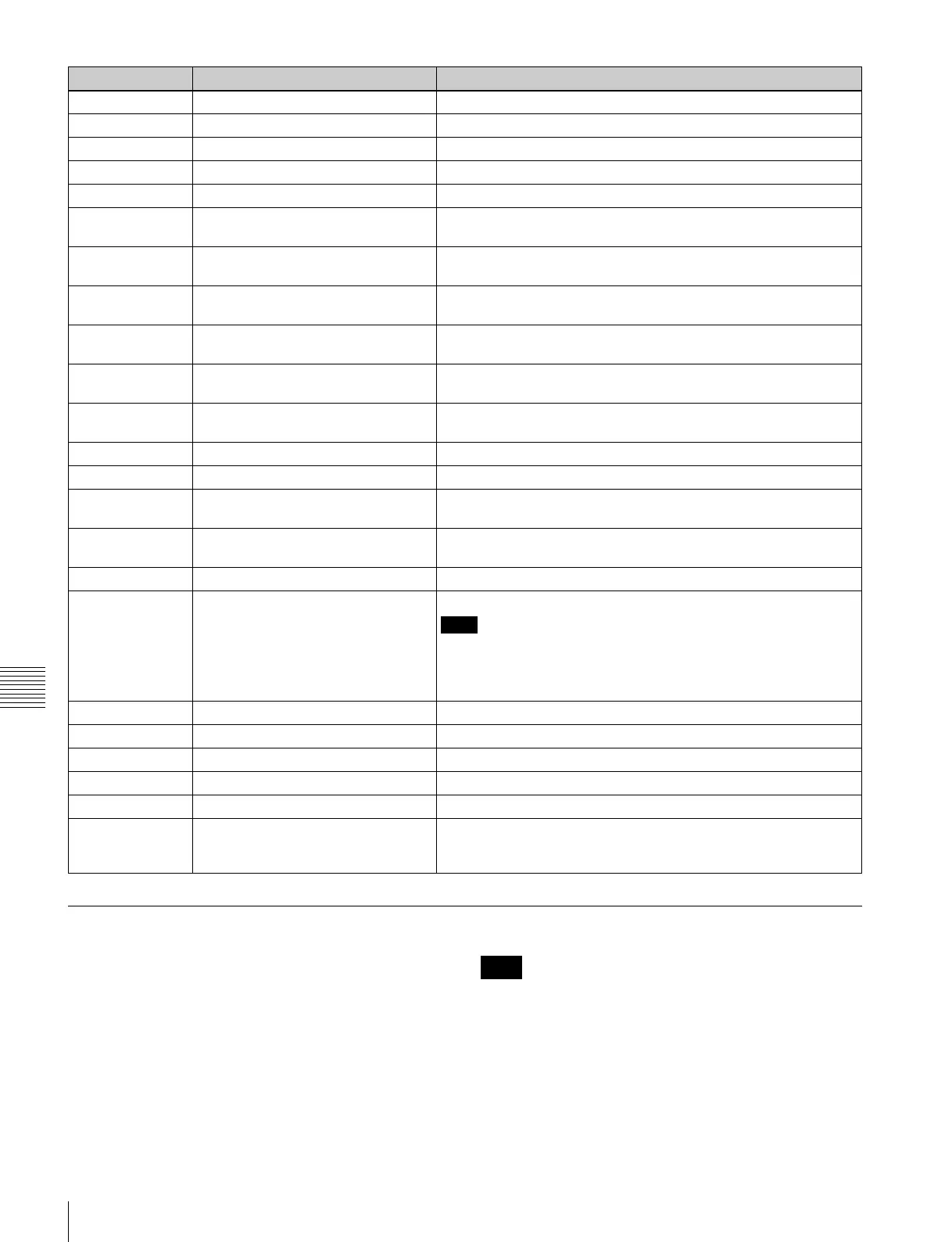
10 HUMID DETECT Condensation was detected.
11 TOP END BOTH DETECT The tape beginning and tape end were detected at the same time.
12 TAPE TOP ERROR A tape beginning sensor fault was detected.
13 TAPE END ERROR A tape end sensor fault was detected.
14 FAN MOTOR ERROR A cooling fan motor operation fault was detected.
20 CC TIME OVER A fault was detected in a cassette compartment raising or lowering
operation.
21 SHIFT TIME OVER A fault was detected movement of the reel table to adjust for
cassette size.
22 POSITION BOTH DETECT The reel table was detected in the L cassette position and S
cassette position at the same time.
23 THREAD BOTH DETECT The threading end and unthreading end were detected at the same
time.
93 DR IF ERROR A communications error between the SV CPU (board SS-95) and
drum CPU (board DR-508) was detected.
97 NVRAM CHECK SUM ERROR An operation fault was detected in the servo system NV-RAM
(board DR-508).
FF SV UNDEFINE ERROR Undefined SV error was detected.
A0 SY UNDEFINE ERROR Undefined SY error was detected.
A2 SY1-SY2 DPRAM ERROR A DPRAM (board SS-95) operation fault between SYS1 and SYS2
was detected.
A5 SY-FC DPRAM ERROR A DPRAM (board FC-91) operation fault between SYS1 and FC
was detected.
A8 SY NVRAM CHECK SUM ERROR A SYS NVRAM (board SS-95) operation fault was detected.
B3 XXX PLDX INITIAL ERROR An initialization error in the PLD was detected.
Note
The description of “XXX” at the beginning of the message and of
“X” immediately after the “PLD” depends on the PLD where the
error was detected.
Display example: SYS PLD1 INITIAL ERROR
B8 SY1-SY2 INTERFACE ERROR A SYS CPU communications fault was detected.
B9 SY-SV INTERFACE ERROR An SV CPU communications fault was detected.
BA SY-EQ INTERFACE ERROR An EQ CPU communications fault was detected.
BB SY-FC INTERFACE ERROR An FC CPU communications fault was detected.
BC SY-50PIN INTERFACE ERROR A communications fault with the 50-pin CPU was detected.
BD SY-CP MISMATCH ERROR A fault was detected in the pairing of the main unit and the lower
control panel. This appears when the lower control panel of another
unit is connected to this unit, for example.
Item number Display Meaning
Note
 Loading...