Do you have a question about the Sony STR-DE235 and is the answer not in the manual?
| Number of Channels | 2 |
|---|---|
| Total Harmonic Distortion | 0.09% |
| Signal to Noise Ratio | 98 dB |
| Preset Stations | 30 |
| Tuning range | FM, AM |
| Frequency Response | 10 Hz - 100 kHz |
| Input Sensitivity | 200 mV (line) |
| Output | Speaker |
| Speaker Load Impedance | 8 ohms |
| Inputs | Tape |
| Outputs | Video |
| Power Output | 100 watts per channel (8 ohms) |
Details on power output and surround mode capabilities.
Specifications for FM and AM tuner performance, including sensitivity and selectivity.
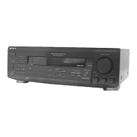
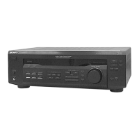
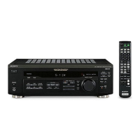
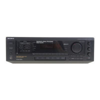
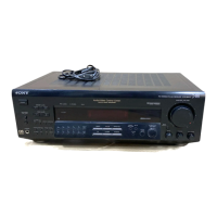
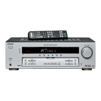
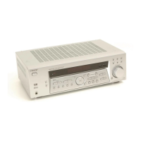
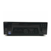
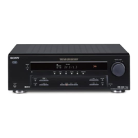
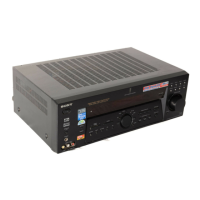
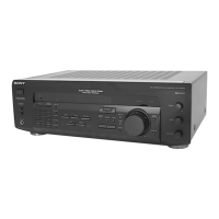
Identifies and labels all front and rear panel controls and connectors.
Procedure for removing the outer case of the unit.
Steps for detaching the front panel assembly.
Clears all preset data, returning the unit to factory default settings.
Activates all segments of the fluorescent display for testing.
Performs auto-scanning and memory function for RDS stations.
Displays the current software version of the unit.
Clears all previously set sound field configurations.
Overview of the unit's functional blocks and signal paths.
Provides guidance on interpreting schematic and wiring diagrams.
Layouts of the printed circuit boards for various sections.
Detailed circuit schematics for main, panel, and tone/volume boards.
Block diagrams of integrated circuits and their pin descriptions.
Diagram showing parts breakdown for the unit's case.
Diagram illustrating the assembly of the front panel components.
Diagram detailing the internal chassis and component layout.
List of electrical components for the display and key boards.
Comprehensive list of components used on the main circuit board.
Components for power switch, primary, secondary, SP SW, standby, and tone boards.
List of electrical components for the tone and volume control boards.