Video Component Hookups
TV or satellite tuner DVD or LD player
i ¸¸¸¸¸
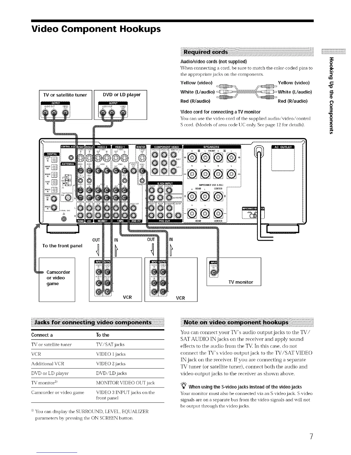
Audio/video cords (not supplied)
When connecting a cord, be sine to match the color coded pins to
tile appropriate jacks oil the components.
Yellow (video) Yellow (video)
White (L/audio) White (L/audio)
Red (R/audio) Red (R/audio)
Video cord for connecting a IV monitor
You can use tile video cord of the supplied audio/video/control
S cord. (Models of area code IIC only. See page 12 for details).
OUT
To the front panel r]
Camcorder
or video
game
_ L FRONT R [] L
÷@@@@+
-@@@@-
IN
VCR
IN
VCR
TV monitor
-T-
O
0
5'
e-
"a
O
O
3
0
Connect a To the
TV or satellite tuner TV/SAT jacks
VCR VIDEO 1 jacks
Additional VCR VIDEO 2 jacks
DVD or LD player DVD/LD jacks
TV monitor 1) MONITOR VIDEO OUT jack
Camcorder or video game VIDEO 3 INPUT jacks on the
fl'ont panel
I)Yon can display the SURROUND, LEVEL, EQUALIZER
parameters by pressing the ON SCREEN button.
You can connect your TV's audio output jacks to the TV/
SAT AUDIO IN jacks on the receiver and apply sound
effects to the audio fl'om the TVi In this case, do not
connect the TV's video output jack to the TV/SAT VIDE(-)
IN jack on the receiver. If you are connecting a separate
TV tuner (or satellite tuner), connect both the audio and
video output jacks to the receiver as shown above.
_'° When using the S-videojacks instead of the video jacks
Your monitor mnst also be connected via an S video jack. S video
signals ale on a separate bus fl'om the video signals and will not
be output through the video jacks.
7