99
Displaying the Monitor Status Page
Chapter 4 Operations
Input Port: Displays Input Port and Input No. set in the
Channel Configuration menu.
RGB Range: Displays RGB Range set in the Channel
Configuration menu.
1080I/PsF: Displays 1080I/PsF set in the Channel
Configuration menu.
Scan Mode: Displays the selected scan mode.
Aspect Mode: Displays the selected aspect ratio.
Interlace Display: Displays On/Off of the interlace
display.
Page 2/4
Information on the picture adjustments is displayed.
Color Profile: Displays Color Profile set in the Channel
Configuration menu.
Color Space: Displays Color Space set in Color Profile
Gamma: Displays Gamma set in Color Profile
Color Temp: Displays Color Temp set in the Channel
Configuration menu.
Picture Preset: Displays Picture Preset set in the Channel
Configuration menu.
Chroma: Displays the Chroma value of the selected
Picture Preset.
Bright: Displays the Bright value of the selected Picture
Preset.
Contrast: Displays the Contrast value of the selected
Picture Preset.
Matrix: Displays Matrix set in the Channel Configuration
menu.
Page 3/4
Information on the ASC CDL and User LUT is displayed.
ASC CDL: Displays whether the ASC CDL data is applied
to the Color Profile setting or not.
File: Displays the file name of the specified ASC CDL
data.
Slope (R/G/B): The slope values of the ASC CDL data
are displayed, in order of R, G, and B, starting from the
left.
Offset (R/G/B): The offset values of the ASC CDL data
are displayed, in order of R, G, and B, starting from the
left.
Power (R/G/B): The power values of the ASC CDL data
are displayed, in order of R, G, and B, starting from the
left.
Saturation: The saturation values of the ASC CDL data
are displayed, in order of R, G, and B, starting from the
left.
User LUT: Displays whether the User LUT data is applied
to the Color Profile setting or not.
File: Displays the file name of the specified User LUT
data.
Color Space: The color space specified in the User LUT
data file is displayed.
Gamma: The gamma specified in the User LUT data file
is displayed.
Page 4/4
When the SDI signal is input
The same information as that of SDI Payload ID Status in
the System Status menu is displayed.
OptionX/InputX: Input port and input connector of the
displayed information
Standard or Option1 to 4 is displayed as an input port, and
Input1 or Input2 is displayed as an input connector.
Payload ID: Displays the 4-byte data for Payload ID of the
SMPTE-352M standard in hexadecimal in sequence of
Byte 1, Byte 2, Byte 3 and Byte 4.
When the Payload ID information is not set, only Current
Status is displayed, and “---” is displayed for other items.
When the following information is not decoded, Unknown
is displayed.
Video Standard: Decode display of Byte 1_Bit 6-0
Sampling Structure: Decode display of Byte 3_Bit 3-0
Bit Depth: Decode display of Byte 4_Bit 1-0
Picture Rate: Decode display of Byte 2_Bit 3-0
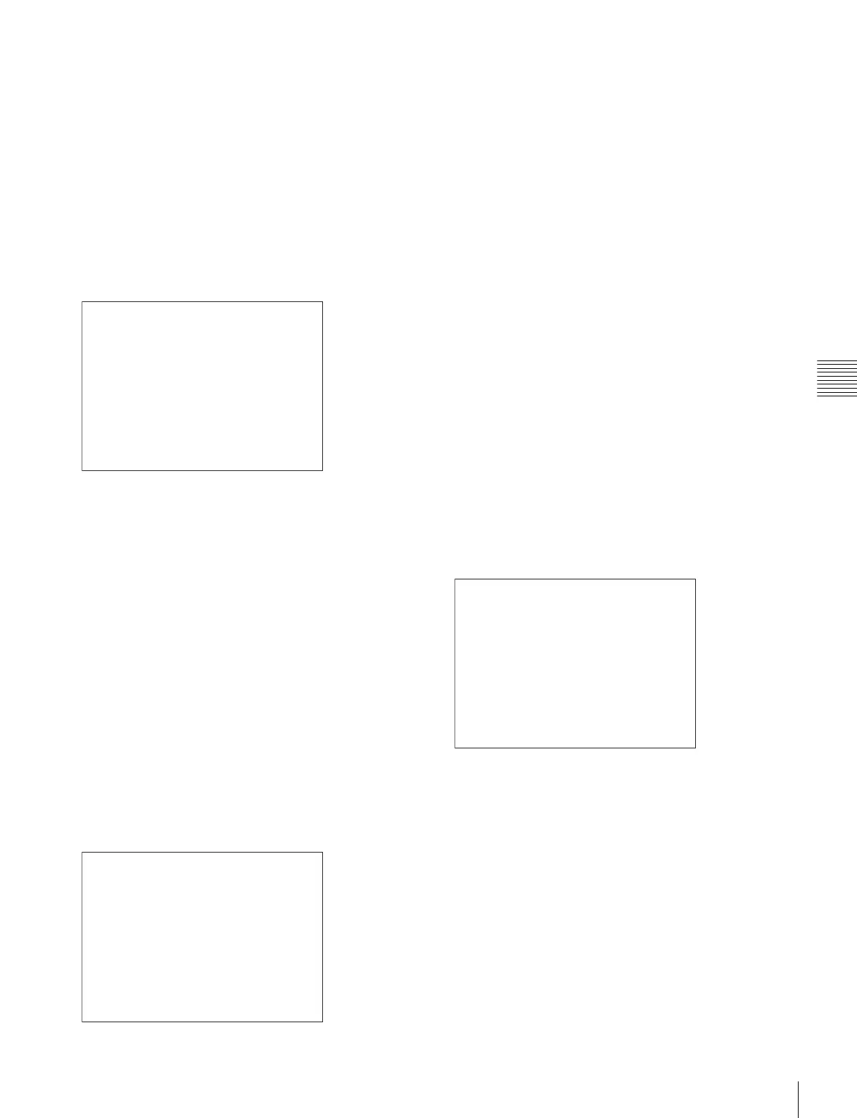
STATUS (Picture Configuration) 2/4
Color Profile
CH01
: BVM EBU
Color Space: EBU
Gamma: CRT BVM
Color Temp: User1
Picture Preset: Preset1
Chroma: 1000
Bright: 000
Contrast: 1000
Matrix: ITU-R BT.709
v
V
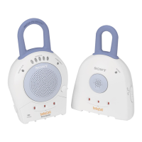
STATUS (ASC CDL, User LUT) 3/4
ASC CDL
CH01
: Applied
File: project 23
Slope (R/G/B):
Offset (R/G/B):
Power (R/G/B):
Saturation:
Color Space:
Gamma:
0.123 0.000 0.000
0.000 0.000 0.000
0.000
Applied
- 0.456 0.000 0.000
User LUT:
File: Slog2Film
2.6
D-Cine
v
V
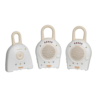
STATUS (SDI Payload ID) 4/4
Option1/Input1
Payload ID B1 B2 B3 B4
Video Standard: HD-SDI
Sampling Structure: 4:2:2 Y/Cb/Cr
Bit Depth: 10bit
Picture Rate: 59.94
Scanning Method: Interlace/Interlace
Link Number: Single/Link_1
Current Status
Format: HD 422 YCbCr 10
I/PsF/P: Interlace
v
V