19
KV-25M2/25T2
Same Level
B-Out Waveform
JW130
11
TUNER
17
L103
IC101
RV101
A
A Board component side
25" 2.21V +/- 0.01V
29" 2.52V +/- 0.01V
R - out Waveform
SUB BRIGHTNESS ADJUSTMENT
1. Input a Phillips colour pattern.
2. Press ‘TEST’ ‘TEST’ 13 on the Remote Commander.
3. Adjust the ‘Sub-Brightness’ data so that there is barely a
difference between the 0 IRE and 10 IRE signal levels.
SUB CONTRAST ADJUSTMENT
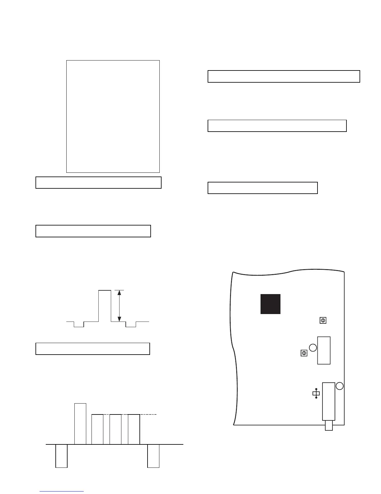
1. Input a video signal that contains a small 100% white area on a
black background
2. Set the picture control to maximum. [‘TT01’]
3. Connect an oscilloscope to Pin 1 of CN504 [A Board].
4. Enter into the ‘Picture’ service menu.
5. Adjust the ‘R - Drive’ data to obtain the following waveform.
SUB COLOUR ADJUSTMENT
1. Receive a PAL colour bar signal.
2. Connect an oscilloscope to Pin 3 of CN504 [A Board].
3. Enter into the ‘Picture’ service menu.
4. Adjust the ‘Sub Colour’ data so that the Cyan, Magenta and
Blue colour bars are of equal levels as indicated below.
Note: Ensure that no signal is applied to the Antenna socket while
carrying out the following IF adjustments.
SYSTEM B/G, D/K, I & L I.F ADJUSTMENT
1. Input a 38.9Mhz carrier signal at 100dBuV to Pin 11 [IF
output] of the tuner [TU101].
2. Measure the voltage at Pin 17 of [IC101].
3. Adjust L103 [A Board] to obtain a voltage of 2.5V +/- 0.3V.
SYSTEM L BAND 1 I.F ADJUSTMENT
1. Input a 34.0MHz carrier signal at 100dBuV to Pin 11 [IF
output] of the tuner [TU101].
2. Select ‘system L’ + C00 [channel 00].
3. Measure the voltage at Pin 17 [IC101].
4. Adjust RV101 [A Board] to obtain a voltage of 2.5V +/- 0.3V.
TUNER AGC ADJUSTMENT
1. Receive a signal of 65dBuV / 75 ohm terminated, via the tuner
antenna socket.
2. Connect a voltmeter to JW130 [A Board].
3. Enter into the ‘Test Menu’.
4. Select the ‘AGC Adjust’ menu item.
5. Adjust the data using the Yellow and Green buttons on the
Remote Commander to obtain a voltage of 3.0V +/- 0.2V.
TECHNICAL
GD - Secam 30
BD - Secam 31
RC - Secam 11
GC - Secam 19
BC - Secam 10
GD - Sports 30
BD - Sports 36
RC - Sports 14
GC - Sports 15
BC - Sports 17
Y - Delay (AV) 07