— 14 —
KV-27FV310/29FV310/32FV310/36FV310
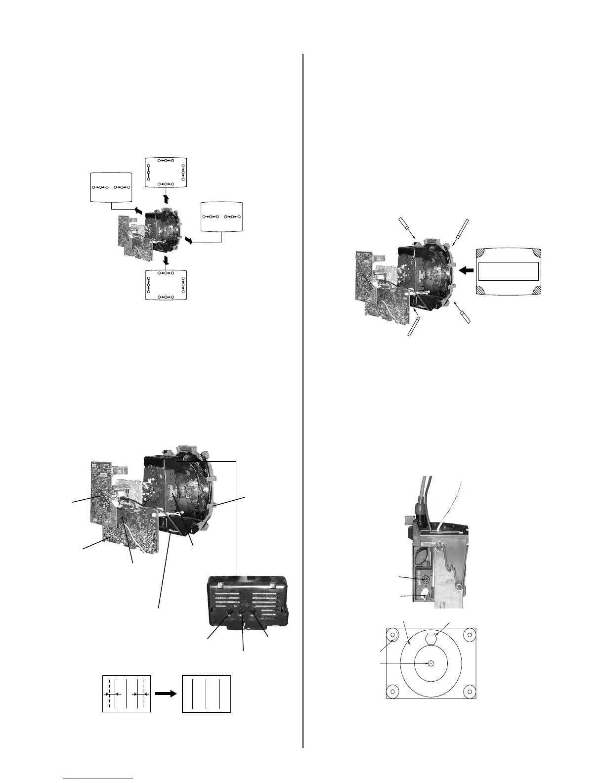
DYNAMIC CONVERGENCE ADJUSTMENT
Before starting, perform Vertical and Horizontal Static Convergence
Adjustment.
1. Slightly loosen deection yoke screw.
2. Remove deection yoke spacers.
3. Move the deection yoke for best convergence as shown below:
R G B
B G
R
R
G
B
R
G
B
B G R R G B
R G B
R
R
R
G
B
G
B
G
B
R G B
B G
R
4. Tighten the deection yoke screw.
5. Install the deection yoke spacers.
TLH PLATE ADJUSTMENT
Preparation:
• Input crosshatch pattern.
• Adjust Picture Quality to standard, Picture and Brightness to 50%, and
Other to standard.
• Adjust the Horizontal Convergence of red and blue dots by tilting the
TLH plate on the deection yoke.
XCV
V Board
RV701
V.STAT
Y Magnet
TLH Plate
H-TRP
YCH
TLV
C Board
TLH+
TLH-
B R
(R)(B)
R B
(B)(R)
1. Adjust XCV core to balance X axis.
2. Adjust YCH VR to balance Y axis.
3. Adjust vertical red and blue convergence with V.TILT (TLV VR.)
Perform adjustments while tracking items 1 and 2.
4. Adjust Y MAGNET to correct V.BOW Geometry Distortion.
5. Adjust H-TRP to correct H.Trapezoid Geometry Distortion.
After adjusting items 4 and 5, conrm overall geometry again.
SCREEN-CORNER CONVERGENCE
1. Afx a permalloy assembly corresponding to the misconverged areas:
ba
c d
a
b
a-d: screen-corner
misconvergence
c
d
2-3. FOCUS
1. Input monoscope signal.
2. Set user controls to normal.
3. Set video mode to STANDARD.
4. Set the PICTURE to maximum.
5. Adjust at 325 Mark for best center/corner focus balance.
6. Receive an entire white signal. Make sure Magenta Ring is at an
acceptable level.
Focus
Screen (G2)
35
325
35 MARK
325 MARK
CENTER
CIRCLE