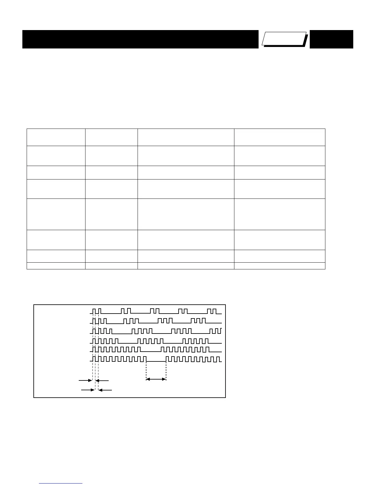
*One ash count is not used for self-diagnostic.
The units in this manual contain a self-diagnostic function. If an error occurs, the STANDBY/TIMER LED will automatically begin to ash. The number
of times the LED ashes translates to a probable source of the problem. A denition of the STANDBY/TIMER LED ash indicators is listed in the
the failure occurrence data stored in memory to reveal past problems and how often these problems occur.
Results for all of the following diagnostic items are displayed on screen. If the screen displays a “0”, an error has occurred.
Diagnostic Item
No. of times
STANDBY / TIMER
lamp flashes
Probable Cause Location Detected Symptoms
Power does not turn on Does not light
� Power cord is not plugged in.
� Fuse is burned out (F601). (GK Board)
� Power does not come on.
� No power is supplied to the TV.
� AC Power supply is faulty.
+B overcurrent (OCP)* 2 times
� H.OUT (Q502) is shorted. (A Board)
� IC702 is shorted. (C Board)
� Power does not come on.
� Load on power line shorted.
+B overvoltage (OVP) 3 times
� IC501 is faulty. (A Board)
� If a high is supplied to pin 2 of IC501.
(A Board)
� Has entered standby mode.
V-Stop 4 times
� +12V is not supplied. (A Board)
� IC561 is faulty. (A Board)
� Has entered standby state after
horizontal raster.
� Vertical deflection pulse is stopped.
� Power line is shorted or power
supply is stopped.
IK (AKB) 5 times
� Video OUT (IC561) is faulty. (A Board)
� IC702 is faulty. (C Board)
� Screen (G2) is improperly adjusted. **
� No raster is generated.
� CRT Cathode current detection
reference pulse output is small.
Zero Cross 9 times
� No zero cross pulses on pin 45
IC1001. (A Board)
� Power does not come on.
9V Check 10 times
� Relay failed (RY600) � Power does not come on.
* If a +B overcurrent is detected, stoppage of the vertical deflection is detected simultaneously. The symptom that is diagnosed first
by the microcontroller is displayed on the screen.
** Refer to Screen (G2) Adjustments in Section 2-4 of this manual