– 9 –
KV-DR29M39/DR29M63/
KV-DR29M69/DR29M89
RM-991
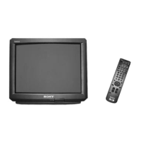
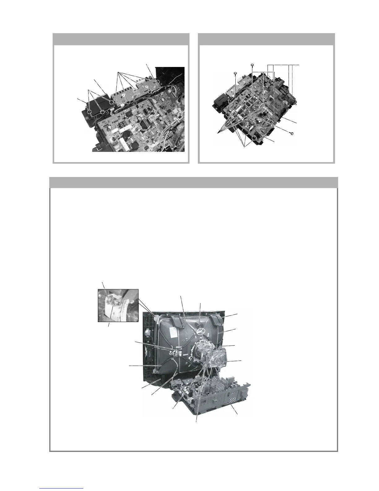
$ Band, DGC(1) Removal (only top-side)
5 Anode Cap Removal
" Bracket Woofer(2) Removal
) Earth Coating Assy(2) Removal
7 Loosen the Neck Assembly
fixing screw and remove
9 Loosen the Deflection Yoke
fixing screw and remove
6 C Board Removal
! Chassis Assy Removal
8 VM Board Removal
( Spring Tension(2)
Removal
# Supports, CRT(2) Removal
& DGC(2) Removal
% Holder, DGC(2) Removal
+ Nut special CRT (4)
~ Nut, Locking (4)
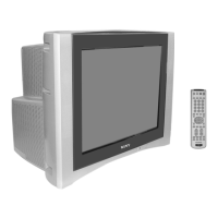
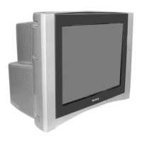
1-11. H1 AND H2 BOARDS REMOVAL 1-12. A AND D BOARDS REMOVAL
3 Three hooks
1 Five hooks
4 Cover, H
2 H1 Board
5 H2 Board
5 One screw
(3 × 12)(+) BVTP
5 One screw
(3 × 12)(+) BVTP
2 Three screws
(3 × 12)(+) BVTP
3 Four hooks
1 Five connectors
6 Four hooks
7 D Board
4 A Board
1-13. PICTURE TUBE REMOVAL
Note:
• The picture tube for OCE model is upside down and the position for the anode cap and tension springs are changed
accordingly. (KV-DR29M39 (OCE) only)
• Please make sure the TV set is not in standing position before removing necessary CRT support located on bottom
right and left.
• When removing the Nut Locking: first make sure to hold the Nut special CRT with a spanner while opening the Nut
Locking using a torque driver. Then proceed to remove the Nut special CRT using a torque driver.
1) Place the TV set with the CRT face down on a cushion (jig).
2) Removal the Rear Cover.
3) Removal the 3D Box.
4) Unplug all interconnecting leads from the Deflection Yoke, Neck Assy, Degaussing Coils and CRT grounding strap.