– 17 –
KV-DR29M39/DR29M63/
KV-DR29M69/DR29M89
RM-991
SECTION 6
CIRCUIT ADJUSTMENTS
6-1. ADJUSTMENTS WITH COMMANDER
Service adjustments to this model can be performed using the
supplied Remote Commander RM-991.
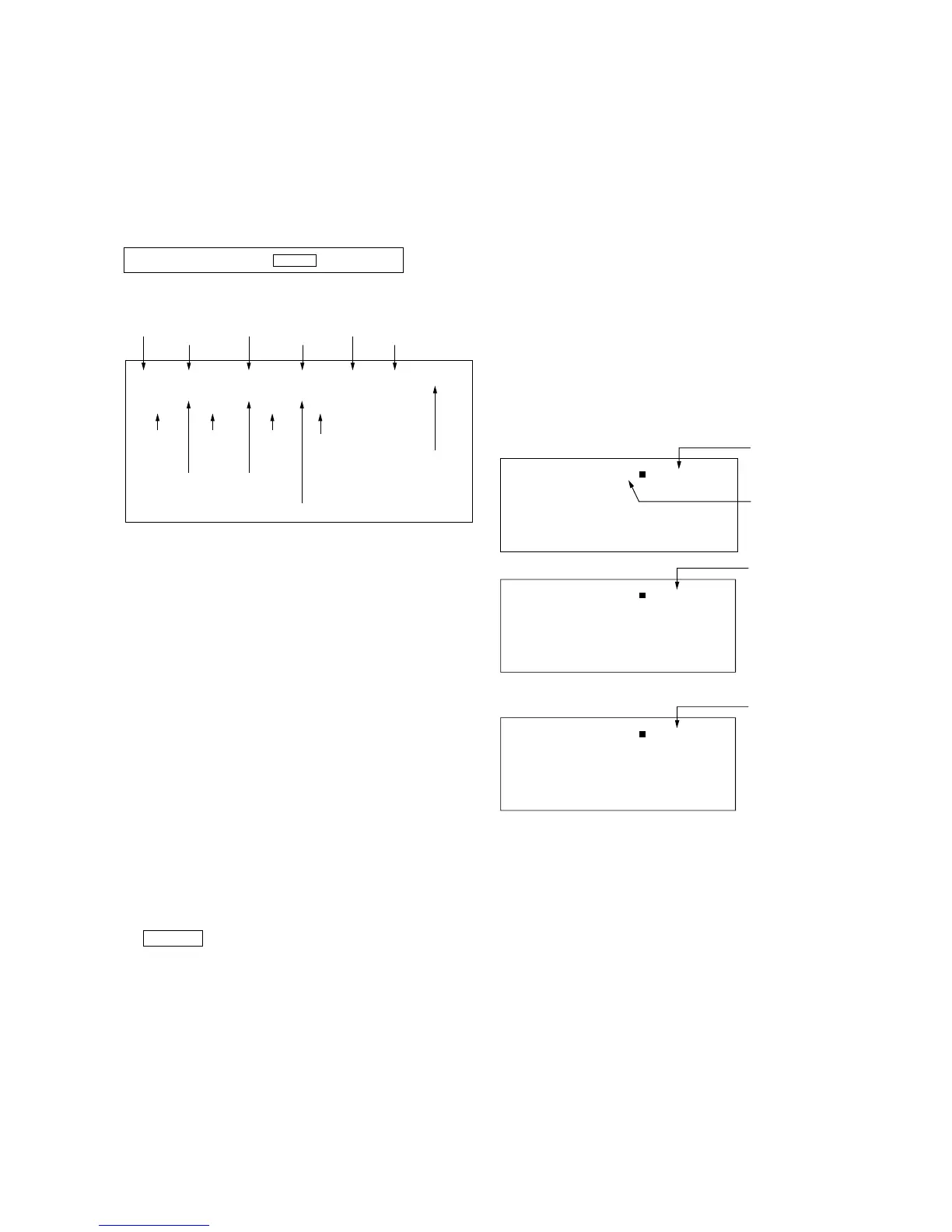
a. ENTERING SERVICE MODE
With the unit on standby
The screen display is :
b. CANCELLATION OF SERVICE MODE
Set the standby condition (Press [POWER] button on the commander),
then press [POWER] button again, hereupon it becomes TV mode.
c. METHOD OF WRITE INTO MEMORY
1) Set to Service Mode.
2) Press 1 (UP) and 4 (DOWN), to select the adjustment
item Name.
3) Press 3 or 6 to raise/lower the data value.
4) Press [MUTING] button to indicate WRITE on the screen.
5) Press - button to write into memory.
d. OTHER FUNCTION VIA REMOTE COMMANDER
7, - All the data becomes the values in memory.
8, - All goes to the standard state.
5, - Service data initialization (Be sure not to use
usually.)
[DISPLAY], - Write 50Hz adjustment data to 60Hz, or vice
versa.
2, - Copy and write all data.
Cursor +/– Skip category (device) to category (device)
example : GEO 00 VSZ
↕
DAC 00 HCT
e. MEMORY WRITE CONFIRMATION METHOD
1) After adjustment, pull out the plug from AC outlet, and then
plug into AC outlet again.
2) Turn the power switch ON and set to Service Mode.
3) Call the adjusted items again to confirm adjustments were
made.
n
[DISPLAY] n 5 n VOL (+) n [POWER]
Use the same method for all Items.
Note : 1. In [WRITE], the data for all items are written into
memory together.
2. For adjustment items that have different standard data
between 50Hz or 60Hz, be sure to use the respective
input signal after adjustment.
6-2. ADJUSTMENT METHOD
Item Number 00 of device GEO
This explanation uses V-size as an example.
1. Select “GEO 00 VSZ” with the 1 and 4 buttons.
2. Raise/lower the data with the 3 and 6 buttons.
3. Select the optimum state. (The standard is 1F for PAL
reception.)
4. Press [MUTING] button to indicateWRITE on screen. (The
display from SERVICE (green display) to WRITE (green
display).
5. Execute the writing with the - button. (The WRITE
display changes to red color while executing and then back to
SERVICE (green display).
6. The WRITE execution is completed.
Example on screen display :-