Page 71 of 98
118157-001 Rev C
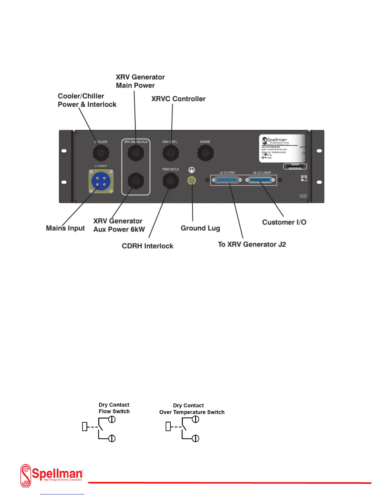
Power Connections (I/O System Interface Box):
Note: Included cables with the I/O Box not shown for the
Generator Power, or XRVC Controller
Connect the ground lug on the rear panel to earth ground. Use a minimum of #10 AWG copper stranded
wire. Remove the top cover of the I/O Box for the Chiller or Cooler Interlock and power cable
installation. The Chiller or Cooler includes instructions for sizing the input power wire and detailing
water or oil flow and thermal interlock connections. Remove the top of the I/O Box and locate TB-4 and
TB-5. Route the input power wires from the Cooler or Chiller through the “Cooler” wire grommet and
connect to TB-4 Terminals 1, 2 and 3. Make sure that #3 is the ground connection from the Cooler or
Chiller. The Cooler or Chiller voltage is normally 230Vac single phase. Consult the manufacturer for
additional information. Connect the interlock switches for temperature and coolant flow from the
Cooler or Chiller through the “Cooler “grommet to TB-5, Terminals 1 and 3. Refer to cutout of I/O Box
diagram for connection locations.
Interlock Switches Cooler/Chiller