1 Introduction Thermo E 200 / 320
104
1.5.3 Combustion air supply
ATTENTION
The combustion air intake opening may not point into
driving direction. It should be arranged to effectively
avoid contaminations as well as snow plastering and
splash water intake. Furthermore the combustion air
intake opening should be protected against object
penetration by installing a grid or other suitable
measures.
Combustion air intake and exhaust fume outlet must be
arranged to ensure that no air pressure difference (e.g.
suction) will occur in any vehicle operating condition.
Permissible dimensions of the optional, application-
depending combustion air intake line must be obtained
from the installation instruction.
Condensation water accumulations must be drained. If
necessary, a condensation water drain hole with a dia-
meter of 4 mm must be implemented.
1.5.4 Exhaust line
The exhaust pipe must be secured to the heater using e.g.
a clamp.
Permissible dimensions of the optional, application-
depending exhaust line are to be obtained from the instal-
lation instruction.
ATTENTION
The heater exhaust pipe port may not be partially or
completely obstructed by leafs, soil, snow, mud, etc.
(this may occur when the vehicle is driving in
reverse). The exhaust pipe port may not point into
driving direction.
Combustion air intake and exhaust fume outlet must
be arranged to ensure that no air pressure difference
(e.g. suction) will occur in any vehicle operating
condition.
If the exhaust line is installed in close proximity to
temperature-sensitive parts, then it must be insu-
lated.
If exhaust fumes exit downwards under the vehicle,
an exhaust gas deflection is absolutely necessary.
CAUTION
For permissible exhaust gas deflections for the
Thermo E 200 heater, see Installation instruction.
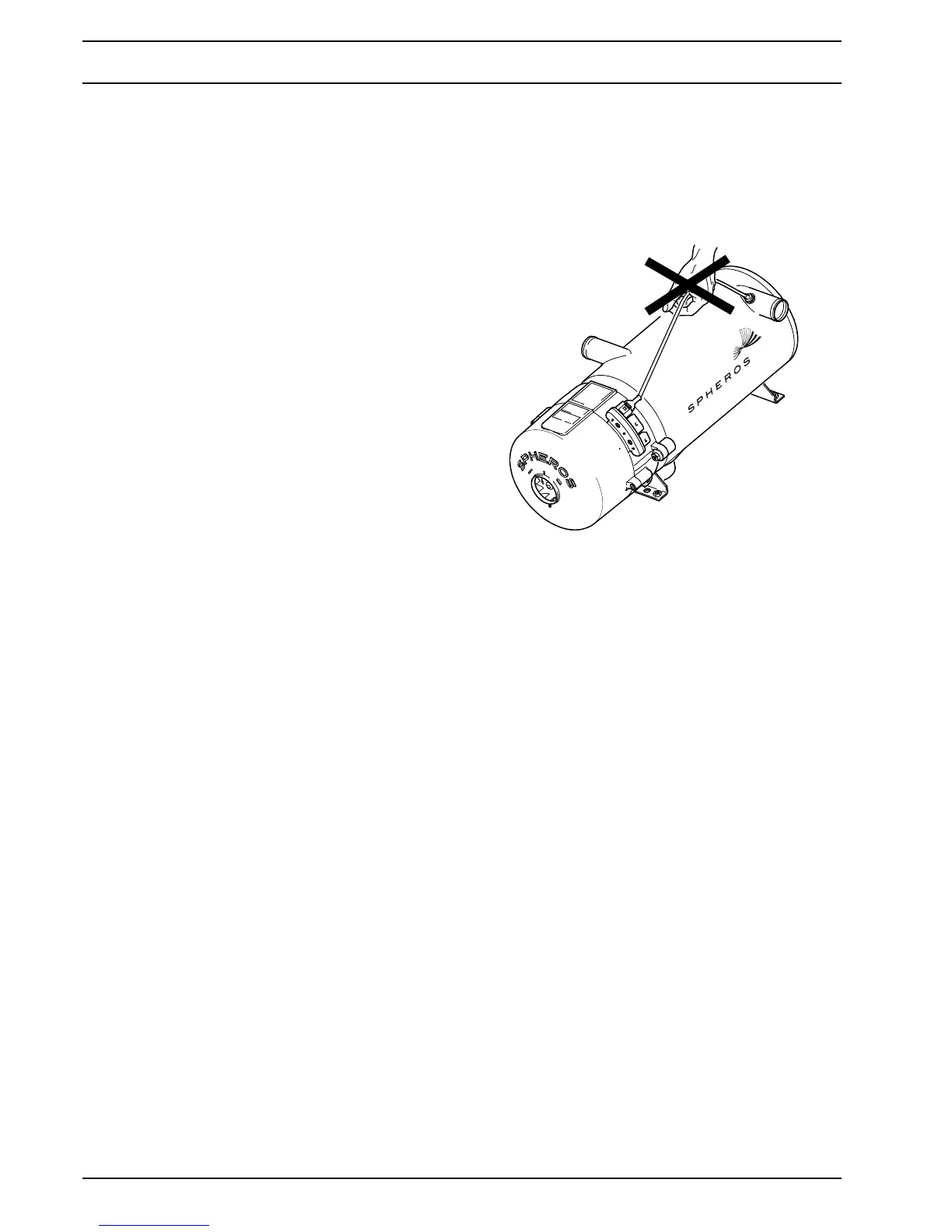
1.5.5 Temperature sensor
ATTENTION
The temperature sensor cable may not be mechani-
cally stressed (pull on the cable, carry the heater at
the cable etc.).
1.6 Suggestions for Improvement and
change
Please direct any complaints, improvement or modifica-
tion suggestions regarding this manual to:
service@spheros.de
STOP!