5 Troubleshooting and error correction Thermo E 200 / 320
512
Manual functional test when disassembled
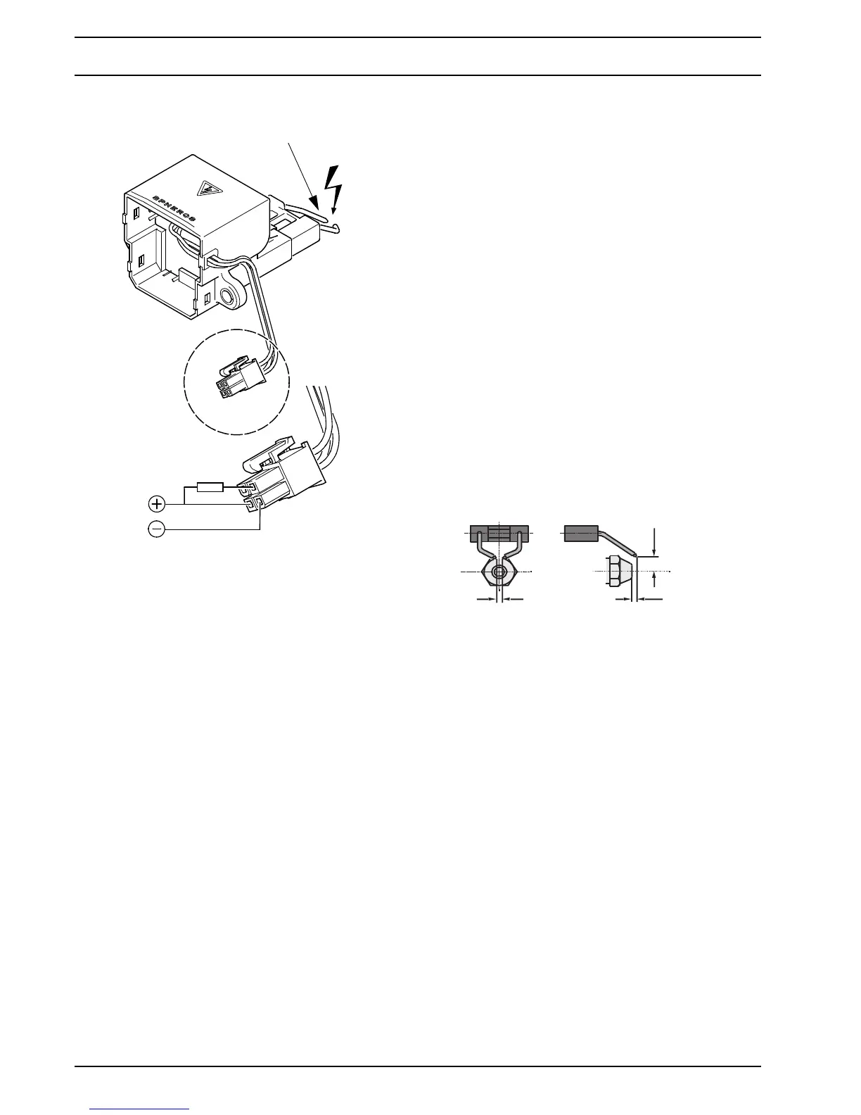
• Remove electronic ignition unit (see 8.6).
• Connect ignition electrode.
• Apply 24V direct voltage according to Fig. 505.
• Nominal condition: Ignition sparks the ignition elec-
trode jump over with a rate of 6Hz.
• After the test is completed, install the electronic igni-
tion unit (see 8.6) and attach the ignition electrode.
• Install burner (see 8.2).
5.5.8 Ignition electrode inspection
NOTE
The ignition electrode insulation may not be damaged.
Ignition electrodes not functioning properly must be
replaced.
ATTENTION
Do not damage the electronic ignition unit when removing
the ignition electrode.
Inspection
• Remove burner (see 8.2)
• Check distance of the electrode tip to the atomizer
nozzle (see Fig. 506).
• Check the distance between the electrodes
(see Fig. 506).
NOTE
The distance between the electrodes may b measured
using checking gauge, item number 310646.
• If needed, lift off ignition electrode (3, Fig. 805) from
the electronic ignition unit by twisting a screwdriver
sideways (see Fig. 804).
• Inspect the ignition electrode insulation for damage.
• Functionality is verified while inspecting the electronic
ignition unit.
5.5.9 Flame detector inspection
NOTE
In case of contamination the glass body of the flame
detector and the inspection glass in the disc
(see Fig. 507) must be cleaned.
The flame detector is permanently integrated into the
control unit and cannot be replaced.
The error diagnosis is possible only via the flash code
(error code 5).
Fig. 505
Ignition electrode 13,000 Volt
10 kOhm
Fig. 506
4
5
8
±0,5
±0,5
+1