5 Troubleshooting and error correction Thermo E 200 / 320
510
5.5 Individual component tests
Individual components can basically be tested using
visual inspection or manual electrical testing.
NOTE
Prior to disconnecting the temperature sensor plug
connection, disconnect the heater from the vehicle
electrical system.
ATTENTION
The general safety regulations according to Chapter 1
must be observed.
5.5.1 General visual inspection
• Inspect components for damages (cracks, deforma-
tion, leaks, discolourations, etc.) and replace as
needed.
• Inspect plugs and cables for corrosion, contact and
crimp errors and repair as needed.
• Check plug contacts for corrosion and tight fit. Repair
as needed.
5.5.2 Heat exchanger visual inspection
• Inspect heat exchanger interior for damage, corro-
sion, sooting and deposits.
• Inspect heat exchanger for outer damage, corrosion,
moisture, deformations, deposits, discolourations,
etc.
ATTENTION
Soot and deposits in the heat exchanger must be
removed, as they impact the heat transfer to the
coolant.
Severe outer deformations may impact coolant flow.
5.5.2.1 Visual inspection of exhaust outlet and
exhaust line
Inspect exhaust outlet and possibly available exhaust line
for conditions, tight fit, contamination and deposits.
Use only exhaust gas deflections according to Installation
instruction.
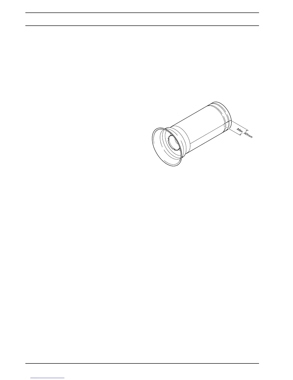
5.5.3 Combustion chamber visual inspection
• Remove combustion chamber (see 8.11).
• Inspect swirl plate and combustion chamber head for
damage and tight fit.
• Check and remove combustion chamber for scalings
and coke deposits as needed.
• Inspect combustion chamber for deformation and
moisture.
• Inspect combustion chamber for cracks.
NOTE
Cracks in longitudinal direction at the end of the
welding seam shorter than 80 mm are permissible.
• After the inspection is completed, reinstall the
combustion chamber (see 8.11).
5.5.4 Resistance check of the temperature
sensor with integrated overheating
protection
CAUTION
Prior to removing the temperature sensor, the over-
pressure in the cooling system must be released by
opening the cooling lid. Observe the risk of injuries
due to increased coolant temperature. Possibly let
heater additionally cool down and have collecting
container ready for discharged coolant.
Inspection
• Inspect temperature sensor, plug and cable for
damage and proper fit.
• Remove temperature sensor (see 8.3).
• Perform the electrical test using a measuring device
suitable for resistance measurements.
• The electrical resistance between pin 1 and pin 3 (see
Fig. 502) is at 0°C 500 Ohm, between pin 2 and pin 3
2000 Ohm. Both resistances change depending on
temperature. The ratio should be at tempered through
sensor 1:4.
• Install temperature sensor (see 8.3).
Fig. 501