Thermo E 200 / 320 8 Repair
803
8.3 Removal and installation of the
temperature sensor with integrated
overheating protection
CAUTION
Risk of injuries if coolant temperature is increased.
Removal
1. Disconnect the heater from the vehicle electrical
system and from the circulating pump as needed.
2. Disconnect the temperature sensor plug (5, Fig. 801).
ATTENTION
The temperature sensor is positioned directly in
the coolant circuit. To prevent coolant from
escaping as far as possible, the coolant hoses are
to be closed with pinch-off pliers (331457).
3. Unscrew and remove temperature sensor (1, Fig.
802). Collect the escaping coolant.
Installation
1. Manually screw temperature sensor (1, Fig. 802) into
coolant outlet (2).
2. Tighten temperature sensor (1) with 8 Nm ± 0.5 Nm.
3. Connect temperature sensor plug (5, Fig. 801).
4. Connect heater with the vehicle electrical system and
the circulating pump as needed.
8.4 Hood removal and installation
Removing the hood provides access to the following
components for maintenance, inspection and repair
purposes:
•Fan
• Burner motor
• Control unit
• Coupling
Removal
1. Disconnect the heater from the vehicle electrical
system.
2. If applicable, disconnect the temperature sensor
(5, Fig. 801).
3. Loosen screws (3, Fig. 801).
4. Remove hood (4).
Installation
1. Place hood (4, Fig. 801) in assembly position. Ensure
centre alignment, proper fit and seal towards heater
wiring harness.
2. Insert screws (3) and tighten with 2 Nm + 0.5 Nm.
3. If applicable, reconnect the temperature sensor plug
(5, Abb. 801).
4. Connect the heater to the vehicle electrical system.
8.5 Burner motor removal and installation
Removal
1. Disconnect the temperature sensor (1, Fig. 802).
2. Remove the burner (see 8.2).
3. Remove the fuel pump (see 8.8).
4. Disconnect the burner motor plug (6, Fig. 803) from
control unit.
5. Remove the cable sleeve.
6. Remove the hood (1).
7. Remove the fan wheel (4). For that remove the shaft
circlip using suitable pliers.
ATTENTION
Do not overstretch the shaft circlip.
8. Remove the three countersunk screws.
9. Remove the burner motor (5).
10. Remove the coupling (7).
CAUTION
If the motor is replaced due to functional failure, also
all plug connections at the control unit are to be
checked and replaced as necessary.
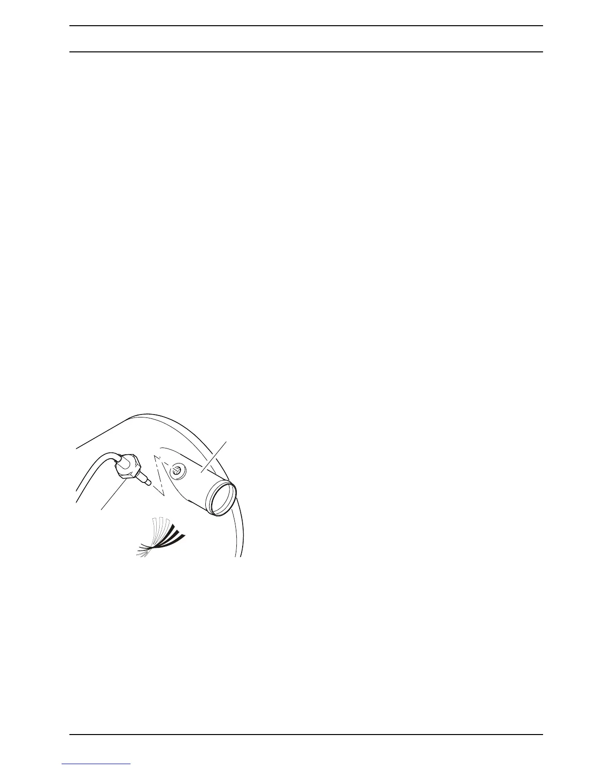
Fig. 802 Temperature sensor removal and installation
1
2
1 Temperature sensor
2 Coolant outlet