3 Description of assemblies and components Thermo E 200 / 320
302
3.1 Burner
The burner consists of components
• Burner motor
• Combustion air fan
• Fuel pump with solenoid valve
• Atomizer nozzle
• Electronic ignition unit with ignition electrode
• Control unit with flame detector
• Disc with inspection glass
• Nozzle block preheater (optional)
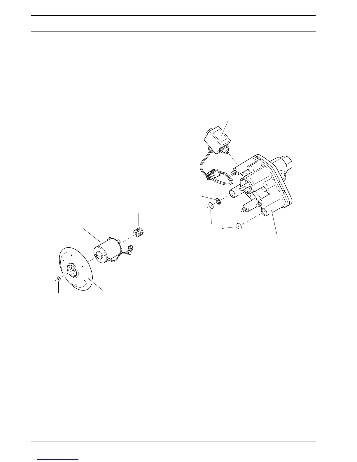
3.1.1 Combustion air fan
The combustion air fan transports the air required for
combustion from the combustion air intake to the combus-
tion chamber.
The combustion air fan consists of burner motor and fan.
Air is drawn in through the air intake opening in the hood.
The air intake opening is equipped with a splashguard, a
protective screen and a hot air elbow.
Two different motors are assigned to the different heating
capacity classes of the Thermo E series. This assignment
is clearly beyond the material number. The motors must
not be interchanged.
NOTE
The positioning of the engine to the housing is safely
defined by a pin and a hole (see Fig. 803).
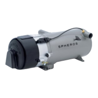
3.1.2 Fuel pump
The fuel pump is responsible for fuel supply.
The pump is driven by the burner motor via a coupling.
Fuel is compressed in the fuel pump to approx. 10 bar and
atomized via the atomizer nozzle.
The solenoid valve integrated into the fuel pump opens
and closes the fuel supply to the atomizer nozzle.
Identical fuel pumps are installed in heaters of both
heating capacity classes.
The fuel pump is designed for dual-line operation (fuel
supply and return line).
ATTENTION
If the heater is operated with
– a long fuel supply line (> 15m)
– check valves in the fuel supply and return line
(> 0,07 bar)
– a fuel filter in the fuel supply line
the fuel supply line and fuel filter are to be filled prior
to first heater start-up (see 8.14.1).
Burner motor
Fan
Shaft
circlip
Coupling
Solenoid valve
Fuel pump
Screen
O-ring