Thermo E 200 / 320 3 Description of assemblies and components
305
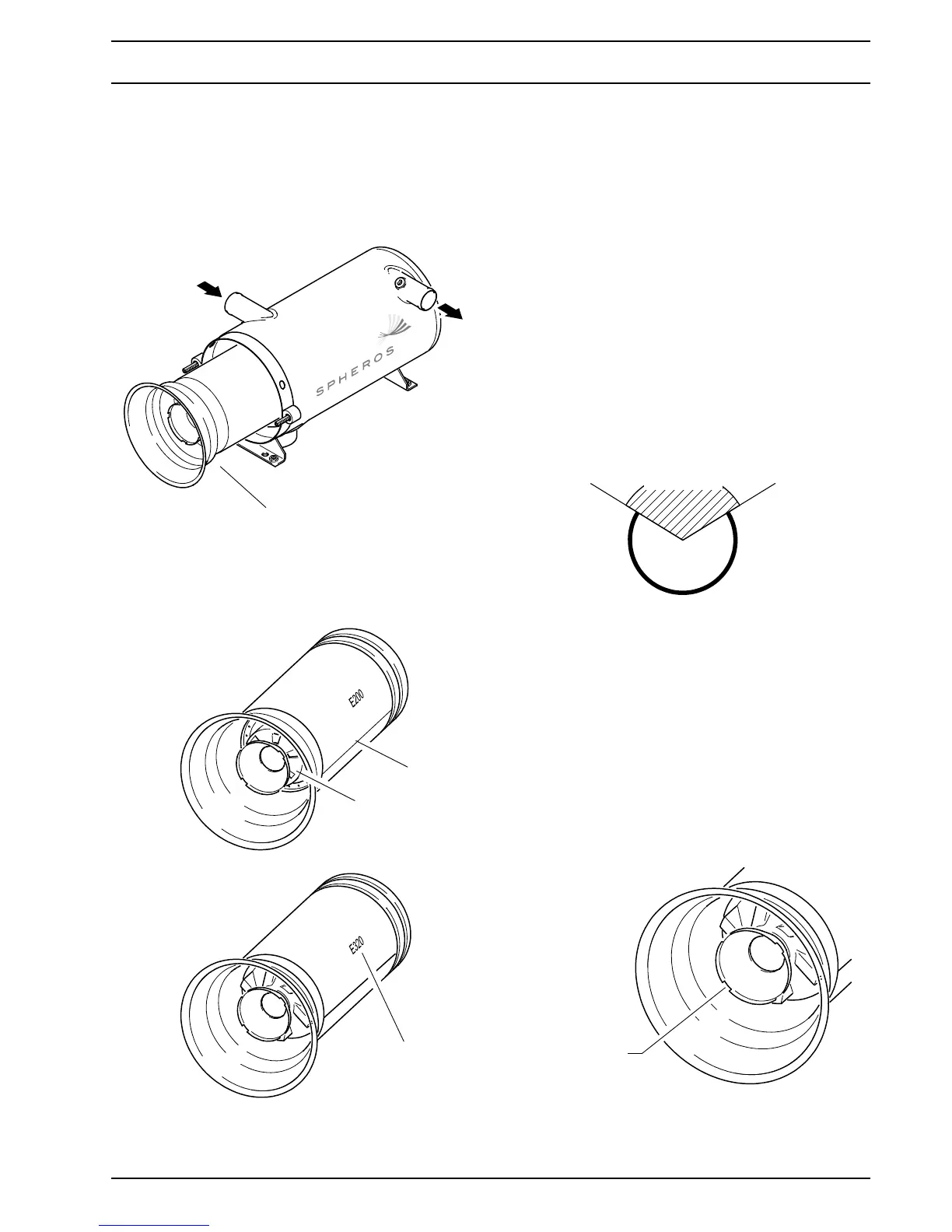
3.3 Combustion chamber
The combustion chamber is used for generation and
combustion of the fuel air mixture. The generated exhaust
gas heats the coolant flowing through the heat exchanger.
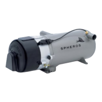
Depending on heating capacity class, different combus-
tion chambers are used.
They have different swirler (E 200 sheet metal, E 320 cast
iron). The combustion chamber of the Thermo E 320 is
additionally equipped with a flame stabilization pipe.
The combustion chambers have an identification stamp
according to the associated heater (E 200 or E 320).
CAUTION
Heater operation with a combustion chamber of a
other heating capacity class is not permitted.
NOTE
The combustion chamber should be inserted into the
heat exchanger in such a way that its welding seam is
positioned between 2 and 10 o clock (not upwards!).
A position change during maintenance is permissible
and affects the expected service life of the combus-
tion chamber positively (see graphic below).
NOTE
It should be ensured that none of the 4 cut-outs of the
combustion chamber head points vertically down-
wards (see graphic below).
Dripping from nozzle fuel is so collected in a reservoir
between disc and burner head and will be burned at
the next burner operation instead to soil the heater.
.
Combustion chamber
Identification
of the heating
capacity class
Welding seam
Swirler
32 KW
20 KW
permissible
not permissible
Position of welding seam
Cut-out positions
on the combustion
chamber head
in installed position