6 Wiring diagrams Thermo E 200 / 320
602
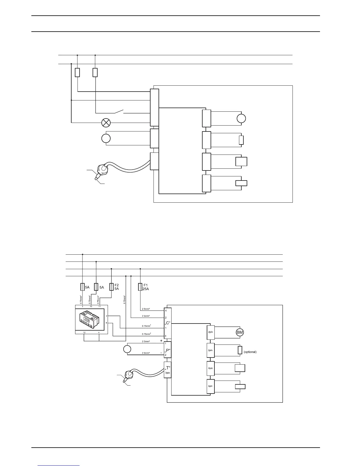
Fig. 601 System wiring diagram for heaters Thermo E, legend see page 603
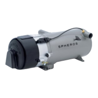
Fig. 602 System wiring diagram for heaters Thermo E with pre-selection timer 1531, legend see page 603
T30
T31
F1
25A
F2
5A
T30
T31
MS
OI
Main Switch
Operating Indicator
Heater Thermo E
BM
CP+
CP-
CP
NPH
(optional)
SV
„C“
„P“
„T“
3pin
1
2
3
4
1
2
EIU
Control Device
2pin
2pin
4pin
6pin
2.5mm²
2.5mm²
2.5mm²
0.75mm²
0.75mm²
2.5mm²
Coolant
Temperature Sensor
Overheating Protection
Cable cross-sections are effective for a maximum cable length of up to 7.5 m. For longer cables see table on page 601.
1
2
Heater Thermo E
T58
T30
T30
T31
T31
MS
CP
CP
CP
OI
T15
Coolant
Temperature Sensor
Overheating Protection
Pre-Selection Timer 1531
Control Device
NPH
EIU
SV
.
.
.
.
.
.
.
.
.
.
Cable cross-sections are effective for a maximum cable length of up to 7.5 m. For longer cables see table on page 601.