5 Troubleshooting and error correction Thermo E 200 / 320
514
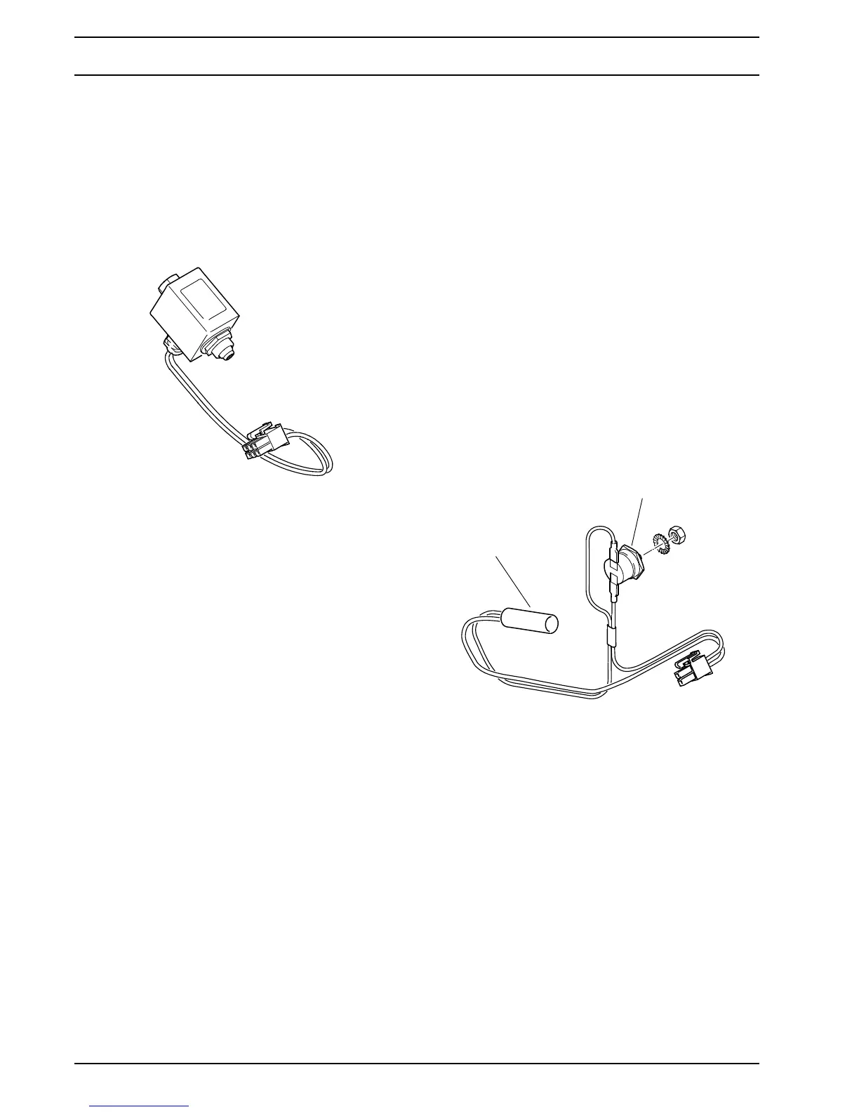
5.5.11 Solenoid valve inspection
ATTENTION
The coil of the solenoid valve can heat up in switched-
on condition.
The solenoid valve must only be completely replaced.
In case of replacement or assembly a new gasket ring
must be used.
NOTE
Due to system characteristics draining the space between
solenoid valve and nozzle bore may cause fuel dripping
from the atomizer nozzle for a short period of time.
A leaking valve seat of the solenoid valve can be indicated
by smoke development in the heater during the purge
cycle. Fuel drips from the atomizer nozzle.
A not closing solenoid valve may cause heater deactiva-
tion during purge cycle with heater interlock activation.
The electrical function of the solenoid valve can be
checked manually.
Manual inspection:
• Remove burner (see 8.2).
• Disconnect the solenoid valve plug from the control
unit.
• Apply 24V direct voltage an check electrical function:
– Opening voltage: ab 17.0 Volt
– Power consumption at
24V and 20°C: 9 Watt
– Nominal current at 24V: 0.37 Ampere
The solenoid valve must audibly open, when voltage
is applied.
• Reconnect the solenoid valve plug to the control unit.
• Install burner (see 8.2).
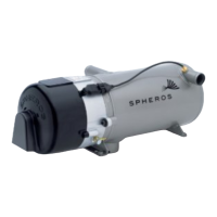
5.5.12 Nozzle block preheater inspection
NOTE
At a temperature of < 5°C the heating element in the
nozzle holder is switched on via a temperature sensor.
The heating duration depends on the intake air tempera-
ture and on the reflected by the burner heat.
Above 8°C the thermostat turns the preheater off.
The power consumption of the heating element is at 24V
approx. 80W.
Inspection
• Remove burner head.
• Disconnect the nozzle block preheater plug from the
control unit.
• Connect an ohmmeter to the plug.
• Bridge over the thermostat
• Resistance max. 8 Ohm.
Fig. 509 Solenoid valve
Abb. 510 Nozzle block preheater
Heating element
Thermostat