Thermo E 200 / 320 8 Repair
805
Installation
1. Position motor (5, Fig. 803) onto the housing (stud at
the housing and hole in the motor flange).
2. Secure motor (5) with three countersunk screws
M5x35 (5 +1 Nm).
3. Install fan (4). Install shaft circlip with suitable pliers.
ATTENTION
Do not use an overstretched shaft circlip!
Ensure secure engagement of the circlip in the
groove!
4. Put the cable through the housing hole and install the
sleeve.
5. Install hood (1) (2 +0.5 Nm).
6. Connect plug (6) of the burner motor with the control
unit.
NOTE
The nozzle block pre-heater plug and the motor plug
may be interchanged.
7. Slide the coupling (7) onto the motor shaft and pre-
position it.
8. Install fuel pump (see 8.8).
9. Install burner (see 8.2).
10. Reconnect temperature sensor (1, Fig. 802).
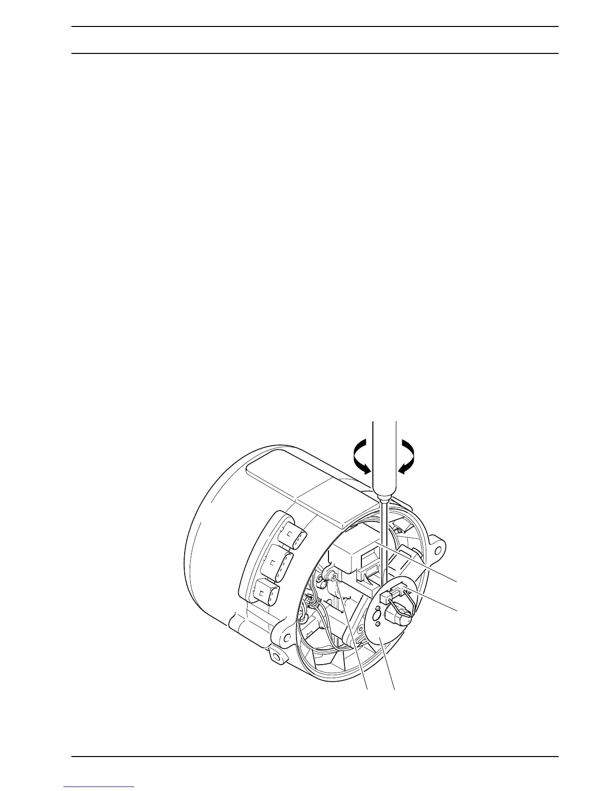
8.6 Electronic ignition unit and ignition
electrode removal and installation
Removal
1. Remove burner (see 8.2).
2. Lift off ignition electrode (2, Fig. 804) from the
electronic ignition unit by twisting a screwdriver
sideways.
3. Remove disc (3).
4. Removes screws (4) with retaining washers.
5. Pull electronic ignition unit (1) off and remove it.
6. If necessary, perform a general visual inspection (see
5.5.1) or test (see 5.5.7).
Installation
1. Bring electronic ignition unit (1, Fig. 804) into
installation position, attach ready for connection and
secure with screws (4).
2. Tighten screws (4) with 5 Nm +1 Nm.
3. Fit disc (5) onto the nozzle holder of the fuel pump (10,
Fig. 805) and align with the flame detector in the
control unit (15, Fig. 805) and the electronic ignition
unit.
4. Fit the ignition electrode (2, Abb. 804).
5. Install burner (see 8.2).
Fig. 804 Removal of the electronic ignition unit / ignition electrode
1
2
1 Electronic ignition unit
2 Ignition electrode
3 Disc
4 Screws (2)
3
4