Operation manual – Spider MINI
39 / 53 rev. 02-01-10-2011
10.8. GEOMETRY ADJUSTMENT
If you do not have necessary tools and expertise, have this work performed by an authorized service centre.
Before adjusting the geometry it is necessary to have the steering chain properly tensioned.
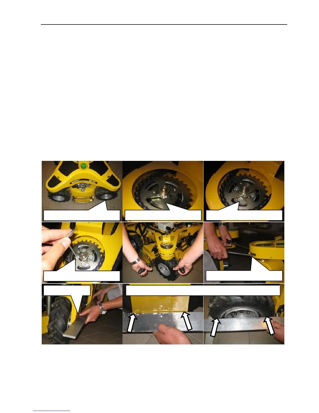
Geometry adjustment instructions
Support the mower at the places marked by the chain symbol so that the wheels are freely in the air.
Turn the wheels in a straight direction.
Release the hydraulic drive by-pass bolt by 1 revolution.
Manually turn the wheels so that the drive sprocket does not cover the taper lock screws.
Release 4 M6 screws of the taper lock by 1 revolution.
Dismount the handles.
Use a screwdriver to lift and release the chain sprocket from the taper lock. The wheel suspension will
now freely turn around its axis. In the same way release all suspensions, which you desire to align.
By placing a straight lath to the wheel housings on the left side and tyre discs on the right side adjust all
wheels to be parallel.
Slightly tighten the screws of the taper lock and check the geometry with the lath.
Tighten the taper lock screws and secure the chain sprocket. Tightening torque is 15 Nm.
Close the hydraulic by-pass bolt.