48
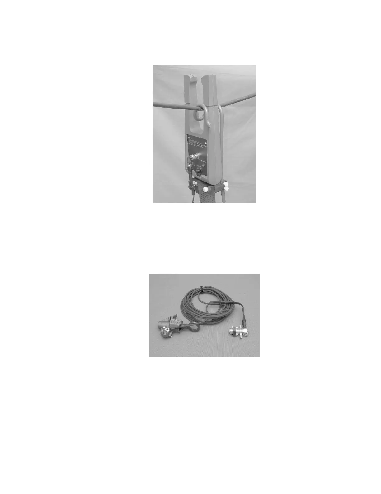
Step 10—Be sure that the conductor(s) is/are placed within the 2x2 window in the trough of the
probe head. The best probe placement is below the probe hanger as pictured since that is where the
high voltage probe head is calibrated.
Proper Conductor Placement
Step 11—At higher voltages, the Grounding Strap is used with the 1500 High Voltage Kit. Attach
the ground clamp end to the ground at the bottom of the pole. Take the other end with a nut and
screw and remove the nut, pass the fiber optic cable through the open portion of the screw and
apply the nut back to the screw. Only hand tighten the nut.



 To Next Page