IM-P343-35 CTLS Issue 5
15
SP500 Electropneumatic Smart Positioner
-
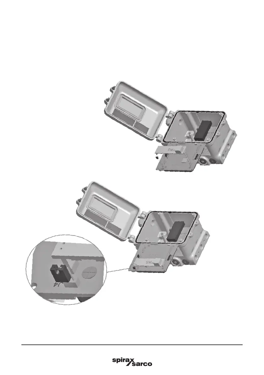
Insert the power supply option board. Collocate Jumper J4 as shown in Figures 15 and 16.
-
Rotate the mainboard to the initial position, x it with the 4 screws, close the positioner and switch on
the power supply and air supply.
Once the option board is mounted, the positioner shall be powered according to the 4 wires connection
diagram, refer to Section 6.2.3, '4 wires electrical connection'. The positioner won't work if powered according
to the standard 2 wires connection.
Fig. 15
Fig. 16