IM-P706-03 CTLS Issue 1
42
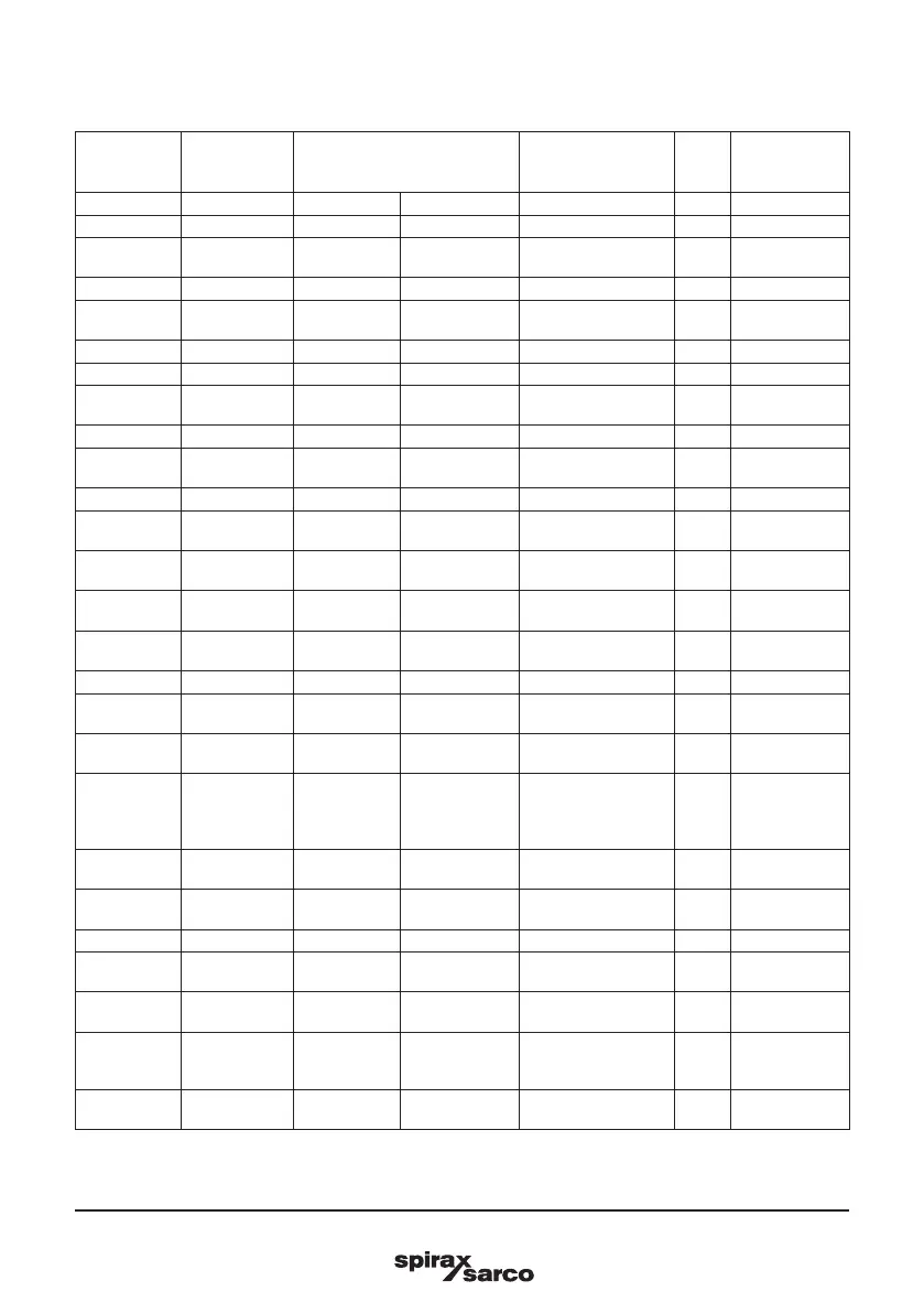
SP7-20 Smart Positioner
Parameter Display Function
Possible
parameter
setting
Unit
Factory
setting
P7._ CTRL_PAR
P7.0 KP UP KP value, up KP value (up) 0.1 to 120.0 --- 5.0
P7.1 KP DN
KP value,
down
KP value (down) 0.1 to 120.0 --- 5.0
P7.2 TV UP TV value, up TV value (up) 10 to 450 --- 200
P7.3 TV DN
TV value,
down
TV value (down) 10 to 450 --- 200
P7.4 Y-OFS UP Y offset, up Y offset (up) 0.0 to 100.0 % 48.0
P7.5 Y-OFS DN Y offset, down Y offset (down) 0.0 to 100.0 % 48.0
P7.6 TOL_BAND
Tolerance
band (zone)
Tolerance band
(zone)
0.3 to 10.0 % 1.5
P7.7 DEADBAND Deadband Dead band 0.10 to 10.00 % 12:10 AM
P7.8 DB_APPR
Deadband
Approach
Dead-band
approach
SLOW, MEDIUM,
FAST
P7.9 TEST Test Test Function --- INACTIVE
P7.10 DB_CALC
Deadband
calculat.
Dead-band
determination
ON, OFF --- ON
P7.11 LEAK_SEN
Leakage
sensivity
Leakage
sensitivity
1 to 7200 S 30
P7.12 CLOSE_UP Pos. time out
Position
monitoring
0.0 to 100.0 % 30.0
P7.13 EXIT Return
Return to
operating level
Function --- NV_SAVE
P8._ ANLG_OUT
P8.0 MIN_RGE Min. range
Min. current
range
4.0 to 18.4 mA 4.0
P8.1 MAX_RGE Max. range
Max. current
range
20.0 to 5.7 mA 20.0
P8.2 ACTION Action
Direction
of action of
characteristic
curve
DIRECT, REVERSE --- DIRECT
P8.3 ALARM Alarm current Alarm message
HIGH_CUR,
LOW_CUR
--- HIGH_CUR
P8.4 RB_CHAR
Readback
character.
Converted
characters
DIRECT, RECALC DIRECT
P8.5 TEST Test Test Function --- NONE
P8.6 ALR_ENAB
Alarm function
enabled
Alarm via
analog output
ON, OFF --- ON
P8.7 CLIPPING Current signal
Actuator
position
LEVER, STEM --- LEVER
Signal
clipping
range
Extension of
signal output to
3.8 to 20.5 mA
4.0 to 20.0;
3.8 to 20.5
mA
mA 4.0 bis 20.5 --- NV_SAVE
P8.8 EXIT Return
Return to
operating level
Function --- ---
5.2.1 SP7-20 Parameter description HART (continued)

 Loading...


