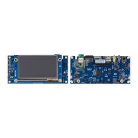
Do you have a question about the ST STM32H7B3I-DK Discovery and is the answer not in the manual?
| Brand | ST |
|---|---|
| Model | STM32H7B3I-DK Discovery |
| Category | Microcontrollers |
| Language | English |
Explains the meaning of the product order code and its components.
Lists the necessary hardware and software for the development environment.
Specifies the IDEs and compilers supported for development.
Details the preloaded software for demonstrating board peripherals.
Overview of the integrated STLINK-V3E for programming and debugging.
Instructions for installing necessary drivers for the STLINK-V3E.
Process for updating the firmware of the embedded STLINK-V3E.
Guide on using external debug tools with the board.
Details powering the board via the onboard STLINK-V3E USB connector.
Explains how to power the board using an external 7-12V VIN supply.
Describes powering the board using a standard 5V USB charger.
Details powering the board via the USB OTG HS connector.
Explains the internal SMPS/LDO configurations for MCU power.
How to measure the MCU's current consumption.
Details the available clock sources for the MCU.
Describes the 4.3-inch touchscreen LCD module and its interface.
Covers the high-speed USB OTG capabilities and connector.
Details the external I2C connector for module expansion.
Information about the microSD card slot and its interface.
Explains the audio codec and available audio connections.
Describes the CAN FD interface and its configuration.
Details the 512-Mbit Octo-SPI NOR Flash memory device.
Information on the external 128-Mbit SDRAM.
Explains the Virtual COM port functionality over USART1.
Information on the TAG connector for debugging and programming.
Describes the function of the board's buttons and LEDs.
Details the integrated Wi-Fi module and its features.
Pinout and function of the USB connector for STLINK-V3E.
Pinout and function of the USB OTG HS connector.
Details the microSD card slot and its pinout.
Pinout and purpose of the STMod+ expansion connector.
Pinout for connecting an 8-bit camera module.
Pinout of the TAG connector for debugging.
Details the external I2C connector for interface monitoring.
Pinout for the audio MEMS daughter extension connector.
Pinout for connecting the 4.3-inch TFT LCD touchscreen.
Pinout for ARDUINO Uno V3 compatible connectors.
Pinout for the stereo audio green jack (headphone output).
Pinout for the stereo audio blue jack (audio line input).
Information on product order code, identification, and board references.
Details product identification, silicon revisions, and limitations.
Lists revisions of the main board and daughterboards.
FCC compliance information and statements.
ISED Canada compliance information and statements.
 Loading...