5
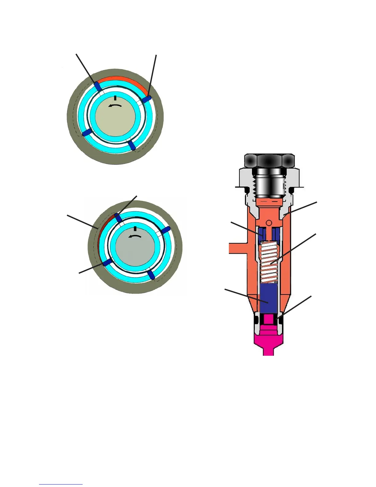
Fig. 1.6b
Blade 1
Blade 2
Fig. 1.6c
Blade 1
Blade 2
Outlet Port
volume between blades 1 and 2 now be-
gins to decrease forcing the fuel charge
into the kidney slot. Pressurization contin-
ues until blade 2 passes out of registry with
the outlet kidney slot.
A small drilling in the face of the porting
plate allows transfer pressure to flow into
the counter bore in the blade carrier where
the blade spring is located. This provides
equal pressure at both ends of the blade
to provide pressure balancing.
E. Transfer Pump Regulator (Figure
1.7)
The DE pump utilizes a transfer pump pres-
sure regulator similar to the type used in
the DS and DB/DC pumps. It consists of a
regulator sleeve that houses a regulating
piston, piston stop, spring and an adjust-
ing plug assembly. The sleeve also incor-
porates a regulating slot and has a filter
screen before the piston stop to prevent
debris from lodging in the regulating slot.
As mentioned earlier, transfer pump pres-
sure is regulated after passing through the
DE and DS pumps as opposed to the other
D series pumps where the pressure is
regulated prior to flowing through the pump.
After filling the various circuits within the
injection pump, the pressurized fuel passes
through the end of the regulator sleeve
Regulating
Sleeve
Assembly
Adjusting
Plug
Assembly
Piston
Stop
Spring
Regulating
Piston
Fig. 1.7