SECTION 3 – CLEANING AND PARTS
INSPECTION
General
The Temperature Sensor and Fuel Control So-
lenoid should be wiped clean and placed in a
parts tray. These items should never be sub-
merged in harsh cleaning solvents or solutions.
The remaining DE pump components can be
cleaned using standard cleaning practices and
solvents that would be used for other
Stanadyne D Series pumps. NOTE: The DE
pump contains many small components. If
parts are put in a wire basket for submersion
in cleaning solution, be sure that the mesh is
small enough so parts will not fall through. After
cleaning, blow-dry all components with clean,
filtered, dry compressed air. Inspect compo-
nents as outlined herein, replace as neces-
sary and dip all parts in clean calibrating fluid
and place in a parts tray.
A. Component Inspection
Discard all o-rings seals, gaskets and adjust-
able spacers. Inspect springs for fretting, wear,
distortion or breakage. Examine all moving
parts for excessive wear, scoring, cracks and
fretting. Replace damaged or excessively worn
parts as necessary. Always check for signs of
contamination. Communicate these findings
with your customer so that he can improve
fuel handling and filtration practices to better
protect his equipment. NOTE: The illustrations
that follow depict typical locations where com-
ponent wear might be observed in DE pumps.
Damage and wear is not limited to these ar-
eas nor is the wear shown meant to indicate
that these parts require replacement. The ap-
pearance of a part is but one measure of
whether the part needs to be replaced. An-
other more important measure is whether the
pump can be calibrated on the test bench.
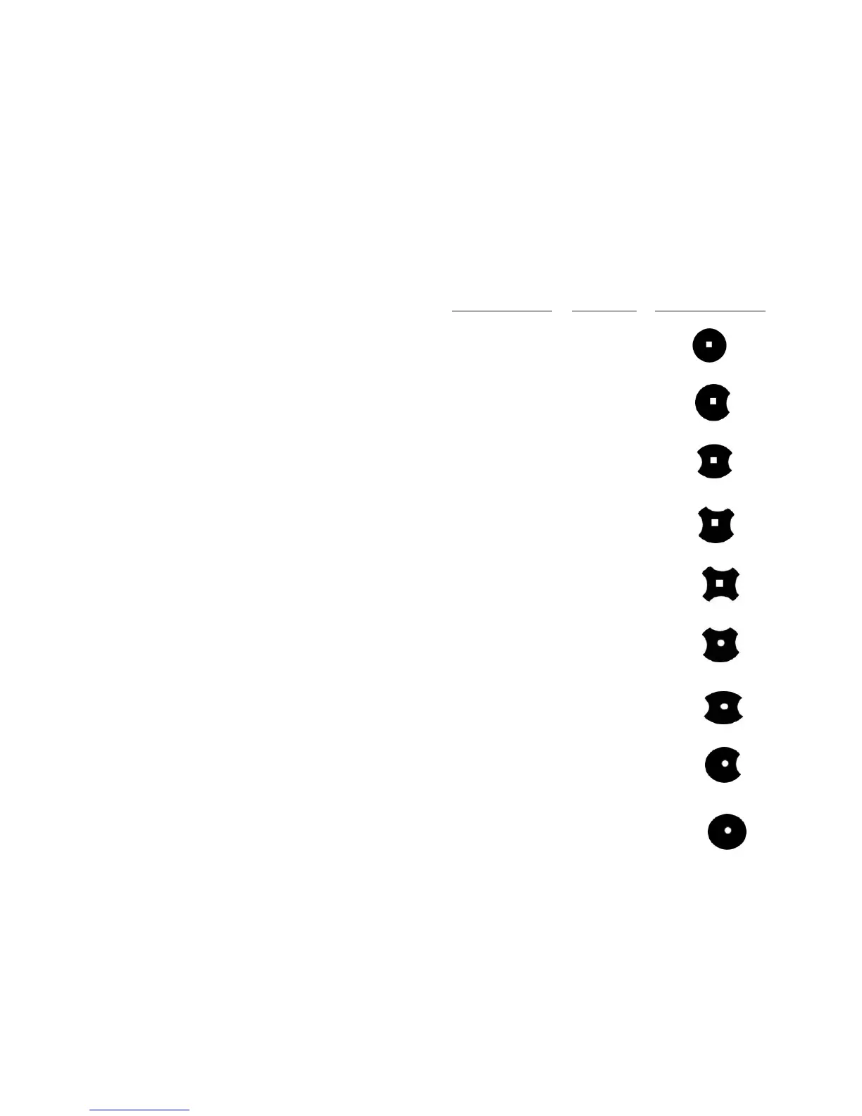
B. Poppet Valve Shims
During disassembly the poppet valve shim(s)
should have been removed and their thick-
ness measured and noted. If they are subse-
quently misplaced, replacement shims are
available as noted and on individual specifi-
cation. Always use the same thickness shim(s)
as replacements. (The average shim stack up
is between .048 and .050 inches.)
Thickness
Part number (inches) Configuration
29653 0.010
29654 0.012
29655 0.015
29656 0.018
29657 0.020
29658 0.022
29659 0.025
29660 0.028
29661 0.0305
C. Supplementary Inspection
1. Housing – Inspect the housing for cracks or
signs of damage. Check head locking and lo-
cating screw holes for erosion or other signs of
damage. Inspect the inside of the housing where
25