SECTION 5 - TEST BENCH
REQUIREMENTS AND PROCEDURES
A. Special Test Equipment Requirements
To test the DE pump, the following special test
bench accessories are needed in addition to a
test bench meeting both ISO 4008 standards
as well as Stanadyne‘s requirements as outlined
in the Service Policies and Procedure Manual.
DE pumps are tested with 0.5 mm orifice plate
36951 Low Dead Volume Calibrating Injectors,
having a factory set opening pressure of 250
bar/3500 p.s.i.
Part
Number Description
33497 Transfer Pump Pressure Tap
36260 Drive Adapter Kit
36263 Hall Sensor Kit
36269 Electronic Control Package
36274 Inlet and Return Fitting Kit
36275 Timing Pin
36464 Housing Pressure Tap
70340 High Pressure Pipes
The 36263 Hall Effect Sensor Kit contains a
bracket assembly and a 36262 Hall Effect
Sensor. Only the Hall Effect Sensor is avail-
able seperately for service replacement. (Fig-
ure 5.7)
The 36260 Drive Adapter Kit contains a drive
adapter, a 36258 Four Tooth Wheel and a
36257 Six Tooth Wheel. Both tooth wheels are
available seperately for service replacement.
The 36269 Electronic Control Package con-
tains the following components:
Breakout Cable 36264
DAC Cable 36265
DE Pump Control Module
Laptop Computor
USB, External Floppy Drive
Only the Breakout and DAC cables are avail-
able seperately for service replacement.
Reference Instruction Manual 99851 for addi-
tional details on the 36269 Electronic Control
Package contents and use.
B. Test Bench Mounting Instructions
Pump mounting plates are provided by the vari-
ous test bench manufacturers, not by
Stanadyne. DE pumps use a triangular mount-
ing flange with a 98mm bolt circle and a 50mm
pilot diameter (same as most DB4 pumps).
The drive adapter is the same as used for test-
ing DB2 pumps for the General Motors 6.2/
6.5L apllications.
Step1. Clamp the test bench 19965 pump hold-
ing fixture in a suitable vise and mount the DE
pump to the fixture.
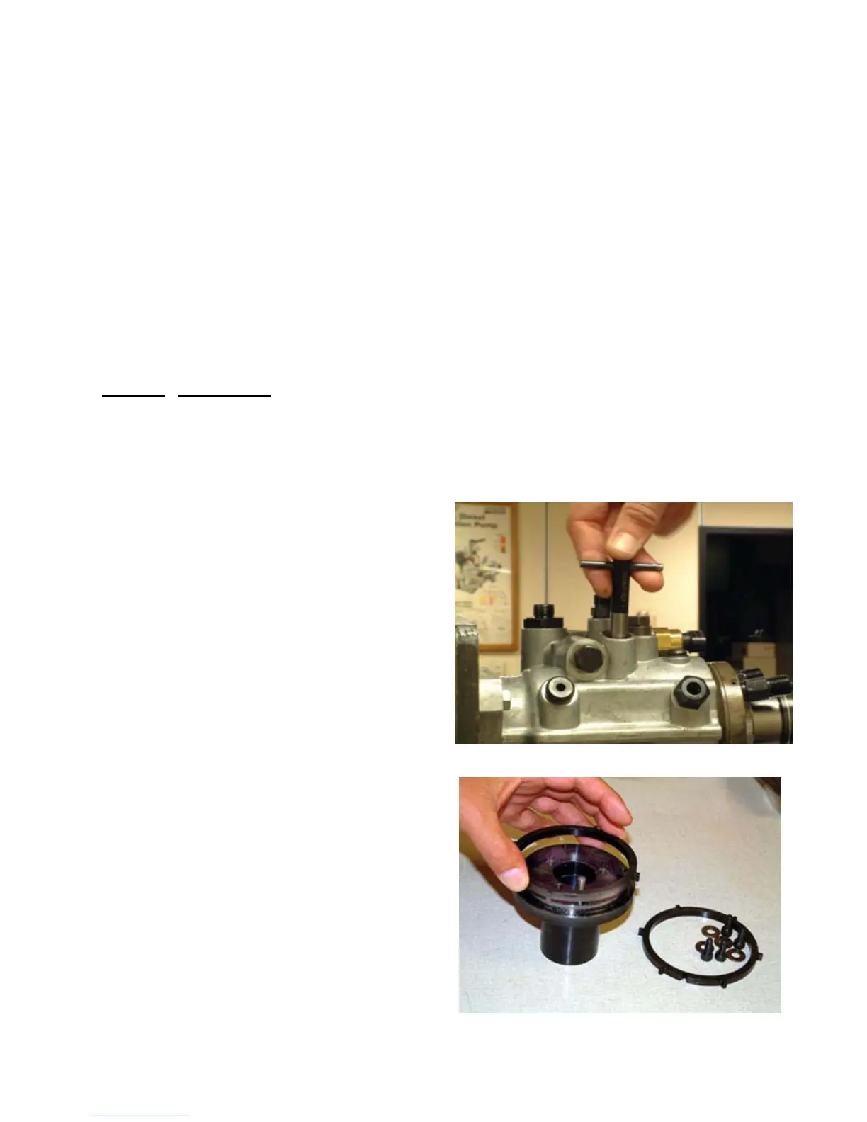
Step 2. Remove the timing access hole plug
from the top of the pump. Insert the 36275
Timing Pin into the bore and slowly rotate the
drive shaft until the pin engages with the slot in
the drive shaft. Ref. Figure 5.1.
Fig. 5.1
Fig. 5.2
46