Lube Oil
Injection Pressure
Housing Pressure
Transfer Pump
Pressure
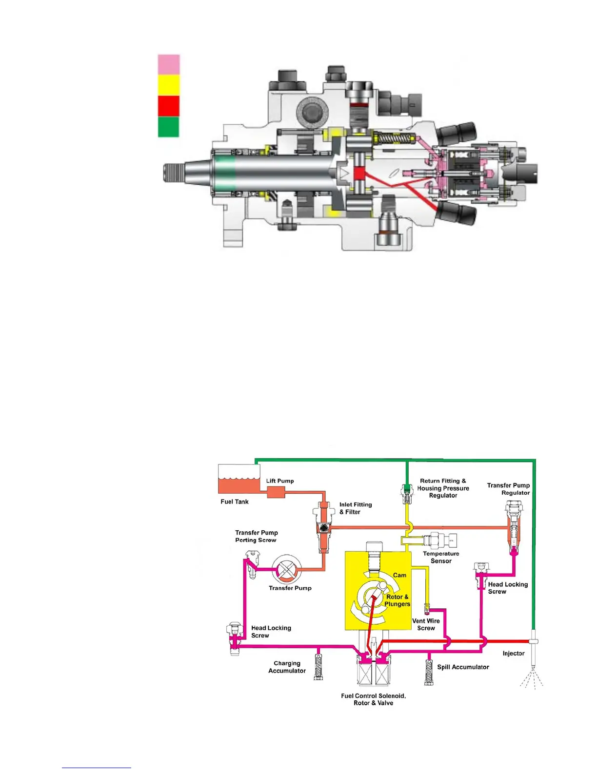
C. Fuel Flow (Figures 1.4 and 1.5)
If so equipped, fuel is drawn from the tank by
a mechanical or electric
lift pump and flows
through a fuel filter and
water separator and
then to the inlet of the in-
jection pump. The lift
pump produces a posi-
tive pressure, but of
more importance, a
solid column of fuel at
the inlet of the injection
pump.
The fuel then flows into
the vane type transfer
pump where it is pres-
surized from 0 to ap-
proximately 160 psi de-
pending on pump
speed.
Pressurized fuel then flows from a transfer
pump porting screw through a passage on
the side of the housing, through the head lock-
ing screw to a passage through the hydraulic
head to the spill chamber. (Pumps with charg-
ing ports also direct this fuel to the charging
annulus in the hydraulic head.) Located be-
tween the head locking screw and the spill
chamber is a passage way that allows fuel
pressure to act on the charging accumulator.
The DE pump has no built-in governor. Gover-
nor regulation, high and low idle speeds, throttle
progression and injection timing are all sensed
and controlled by the ECM hardware and soft-
ware. Injection pump adjustments are limited to
transfer pump pressure and return oil quantity .
Fig. 1.4
3