During discharge the pressure wave
devolped by the pump unseats the plate
allowing unrestricted flow of fuel to the in-
jector. At the end of injection the spring
seats the plate. Any return waves due to
the closing of the injector would need to
pass through the orifice before entering the
pump. The orifice causes an attenuation
of the wave thus lessening the possibility
of a strong secondary wave returning back
to the injector which could cause an engine
damaging secondary injection.
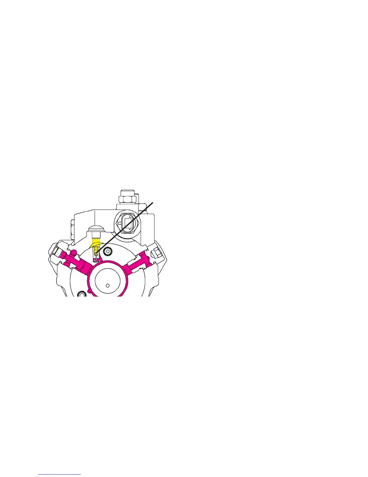
I. Return Fuel Circuit (Figure 1.12)
Fuel fills the DE pump housing due to leak-
age of transfer pump pressure plus injec-
tion pressure between fitted components
within the pump such as the head and ro-
tor assembly, and the pumping plungers.
To adjust this flow to a specific range for
optimum pump operation, and provide a
means of purging any air entrained within
the fuel, a vent wire system is employed.
Fuel under transfer pump pressure is di-
rected into the vent passage at the top of
the hydraulic head which connects with the
housing cavity. Flow through the passage
8
Vent Wire
Fig. 1.12
is controlled by the vent wire assembly.
The amount of return fuel can be adjusted
by varying the wire size used in the vent
wire assembly; the smaller the wire the
greater the flow through the orifice and
vice versa. The vent wire assembly is
available in several sizes in order to pro-
vide adjustment of the return flow to the
quantity called for on the specification.
Note that this assembly is accessible by
removing the button head cap screw be-
tween the two head locking screws.
Since the vent wire assembly is located
in the highest point of the transfer pump
circuit any air entering the transfer pump
gravitates to the vent passage. The air,
plus a small quantity of fuel passes
through the orifice and then from the
housing through the return line connec-
tor and eventually back to the fuel tank.
Housing pressure is maintained by a
spring loaded valve in the return line con-
nector/housing pressure regulator lo-
cated on the top of the pump housing.
The function of the return line connector/
housing pressure regulator is only to con-
trol the pressure within the housing. The
vent wire assembly on the other hand only
adjusts the volume of return flow from the
pump.
J. Dynamic Pump Timing Ad-
vancement (Figure 1.13 and
1.14)
In all pump-line-nozzle fuel injection sys-
tems, the actual beginning of fuel deliv-
ery at the nozzle follows, after a short
period of time, the start of pumping. This
difference between start of pumping and
start of injection,(known as Injection Lag)
is the result of the speed of the pressure
wave through the length of the injection
line. Since the speed of the pressure
wave remains constant (1500 meters/
second for diesel fuel) , injection lag