The operation of the high-speed fuel con-
trol solenoid during charging is pictured in
Figure 1.8. During charging the cam roll-
ers and shoes are riding down the cam
lobes as the rotor rotates. The poppet valve
is open and fuel at transfer pump pressure
is pushing the pumping plungers outward.
Even though filling ends shortly after the roll-
ers reach the base circle of the cam, the
solenoid is still un-energized and the pop-
pet valve is unseated. In pumps also in-
corporating charging ports, these ports are
in registry and are also supplying fuel at
transfer pump pressure to the pumping
chamber.
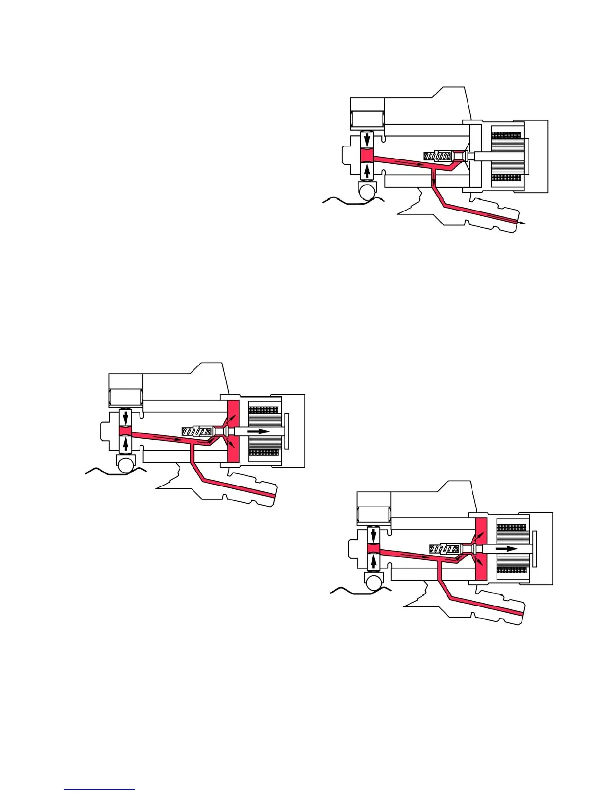
G. Discharging, Spill – Pump – Spill
(Figures 1.9, 1.10, and 1.11)
Further rotor rotation causes the discharge
port of the rotor to start to register with one
of the outlet drillings in the hydraulic head.
When the rollers start to ride up the cam
lobes, the plungers are simultaneously dis-
placed inward. Until current is switched on
to the fuel control solenoid, causing the
poppet valve to seat, displaced fuel is
spilled back into the transfer pump circuit.
As the rollers continue up the cam, the ECM
energizes the fuel solenoid, causing the
poppet valve to seat ending the initial Spill
portion of the discharge event. Fuel now at
injection pressure is forced out the dis-
charge port and drillings in the hydraulic
head, through the discharge fitting contain-
ing a snubber valve and on to the injection
nozzle. The Pump portion of the discharge
event ends when the ECM de-energizes
the fuel control solenoid allowing the pop-
pet valve to unseat and Spill the remain-
der of the displaced fuel back into the trans-
fer pump circuit . The high-pressure accu-
mulator absorbs the resultant pressure
spike from this spill event.
Fig. 1.10
7
H. Snubber Plates
Each DE discharge fitting contains a
snubber plate assembly. The orifice plates
are held on their seats by a light spring.
Spill
Fig. 1.9
Power Off
Valve Open
Power Off
Valve Open
Fig. 1.11
Spill
Power On
Valve Closed
Pump