MANIFOLD
ABSOLUTE
PRESSURE
ENGINE
COOLANT
TEMPERATURE
CRANKSHAFT
REFERENCE
(1 PULSE/CYL)
ELECTRONIC
CONTROL
UNIT
INJECT
PULSE
Return Fuel Temperature
MANIFOLD
ABSOLUTE
PRESSURE
ENGINE
COOLANT
TEMPERATURE
CRANKSHAFT
REFERENCE
(1 PULSE/CYL)
MANIFOLD
ABSOLUTE
PRESSURE
ENGINE
COOLANT
TEMPERATURE
CRANKSHAFT
REFERENCE
(1 PULSE/CYL)
ELECTRONIC
CONTROL
UNIT
INJECT
PULSE
ELECTRONIC
CONTROL
UNIT
INJECT
PULSE
Return Fuel Temperature
mains open during the charging phase of the
pump sequence
The DE hydraulic head assembly contains the
bore in which the rotor revolves, and the charg-
ing and discharge ports, a high-pressure ac-
cumulator to absorb the pressure spikes from
the fuel spilling event and a
low-pressure accumulator to
assist with rotor charging at
high speeds. The head also in-
corporates discharge fittings
each of which contains a snub-
ber plate, snubber seat, snub-
ber spring and retaining screw.
The snubber plates are de-
signed to control the injection
pressure following and between
each injection to prevent sec-
ondary injections or other unde-
sirable injection line pressure
characteristics.
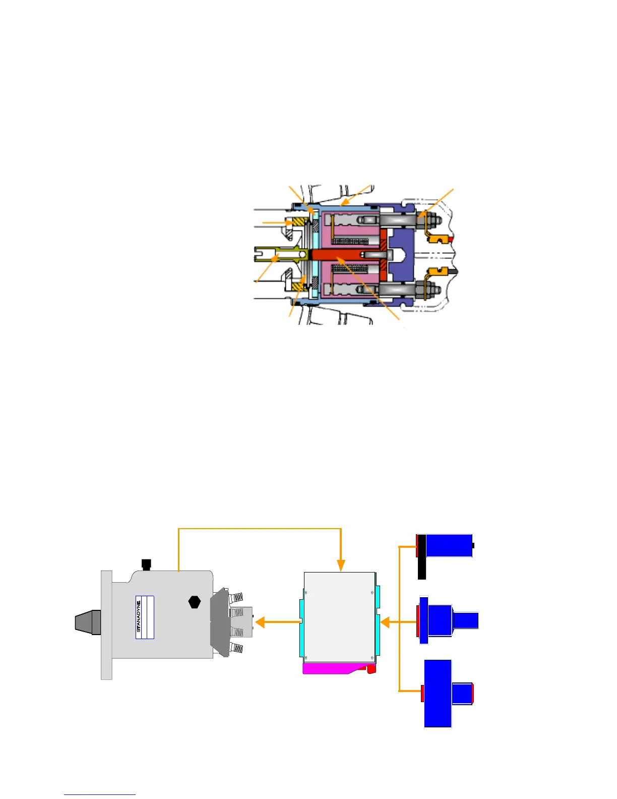
B. Electrical Circuitry (Figure 1.2 and 1.3)
The DE pump only incorporates one sensor, a
thermistor that provides the Engine Control
Module (ECM) with fuel temperature data.
The OEM’s equipment ECM switches current
DE-10
Pump
Fig. 1.2
to the pump solenoid on and off. On the early
part of the pumping cam ramp the solenoid, in
most situations, will remain un-energized allow-
ing the plunger displaced volume to be spilled.
At a precise moment in the discharge se-
quence the ECM energizes the solenoid mov-
ing the armature pin in contact with the rotor
mounted poppet valve causing the valve to seat
and seal. When the poppet valve seals, injec-
tion pumping commences. When the ECM pro-
gram determines that the engine has received
the correct amount of fuel, the current to the
solenoid is interrupted allowing the poppet valve
to unseat spilling the remainder of the fuel
charge. Hence the DE pump has a spill-pump-
spill fueling strategy.
Engine Control
Module
1
2
3
4
5
6
7
1. Armature Pin
2. Poppet Valve
3. Solenoid Terminal (2)
4. Solenoid Assy.
5. Armature Cover
Retainer
6. Adjustable Spacer
Retainer
7. Adjustable Spacer
(Crush Washer)
Fig 1.3
2
Return Fuel Temperature
Crankshaft
Reference (1
pulse/CYL)
Engine
Coolant
Temperature
Manifold
Absolute
Pressure
Inject
Pulse