(when measured in time) remains con-
stant over the full range of engine speeds.
Because injection lag is a constant, as
the engine turns faster, the injection event
will become progressively more retarded
if pump to engine timing is not ad-
vanced.
On most D-Series pumps a hydro-me-
chanical mechanism is typically used to
rotate the cam ring against the direction
of rotation to compensate for this inher-
ent injection lag.
With the DE pump models however, both
timing and delivered fuel quantity can be
controlled with adjustments of the Spill-
Pump-Spill events. Rotation of the cam
ring is not necessary and with it the need
for complex advance mechanisms.
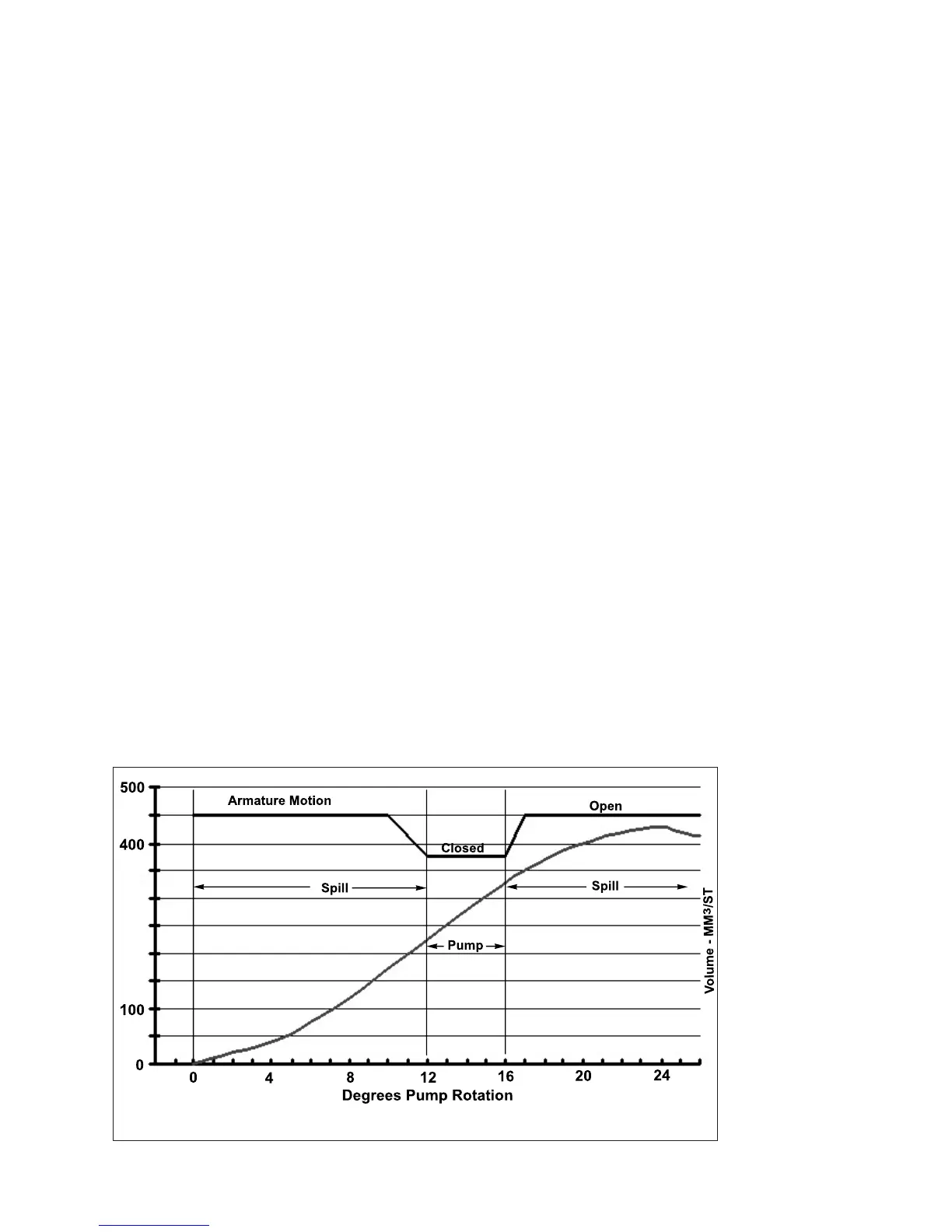
Shown in Figure 1.13 is a hypothetical
cam ring ramp. At 0 degrees of pump
rotation, the ramp of the cam starts to
rise (Line of Symmetry , LOS). From 7
degrees to 18 degrees from the Line of
Symmetry the rise of the cam ramp re-
mains constant creating a constant rate
of delivery (20 mm
3
per degree of pump
rotation in this example). As shown the
pumping event starts at 12 degrees of
pump rotation (Line of Symmetry Start of
Pumping, LOSSOP). At 16 degrees the
second spill event starts, ending the pump-
ing event that lasted a total of 4 degrees
delivering a total of 80 mm
3
of fuel. With an
increase in engine speed, to compensate
for injection lag, pump timing needs to be
advanced. Without a means of rotating the
cam, advancing the injection event is ac-
complished by simply starting the pump-
ing event earlier. For example, instead of
starting at 12 degrees it now starts at 10
degrees. Now the injection pump is start-
ing the pumping event 2 pump degrees (4
engine degrees) earlier. If the engine de-
mand for fuel quantity has remained the
same, in this example 80mm
3
, the start of
the second spill event needs to start 2 pump
degrees earlier to maintain the 4 degree
pumping event. Also note that fuel quantity
can be increased or decreased by short-
ening or lenghtening the duration of the
pumping event.
The OEM’s ECM controls pumping and
spill event timing. The only parameters that
the pump communicates to the ECM are
return fuel temperature and a current inflec-
tion caused by
the solenoid
armature
reaching the
end of its
travel. Pump
to engine po-
sitional rela-
tionship in DE
applications
are fixed and
since the cam
is fixed to the
pump housing,
the engine to
cam relation-
9
Fig. 1.13