SECTION 1 - CONSTRUCTION AND
OPERATION
Model DE Electronic
Fuel Injection Pump
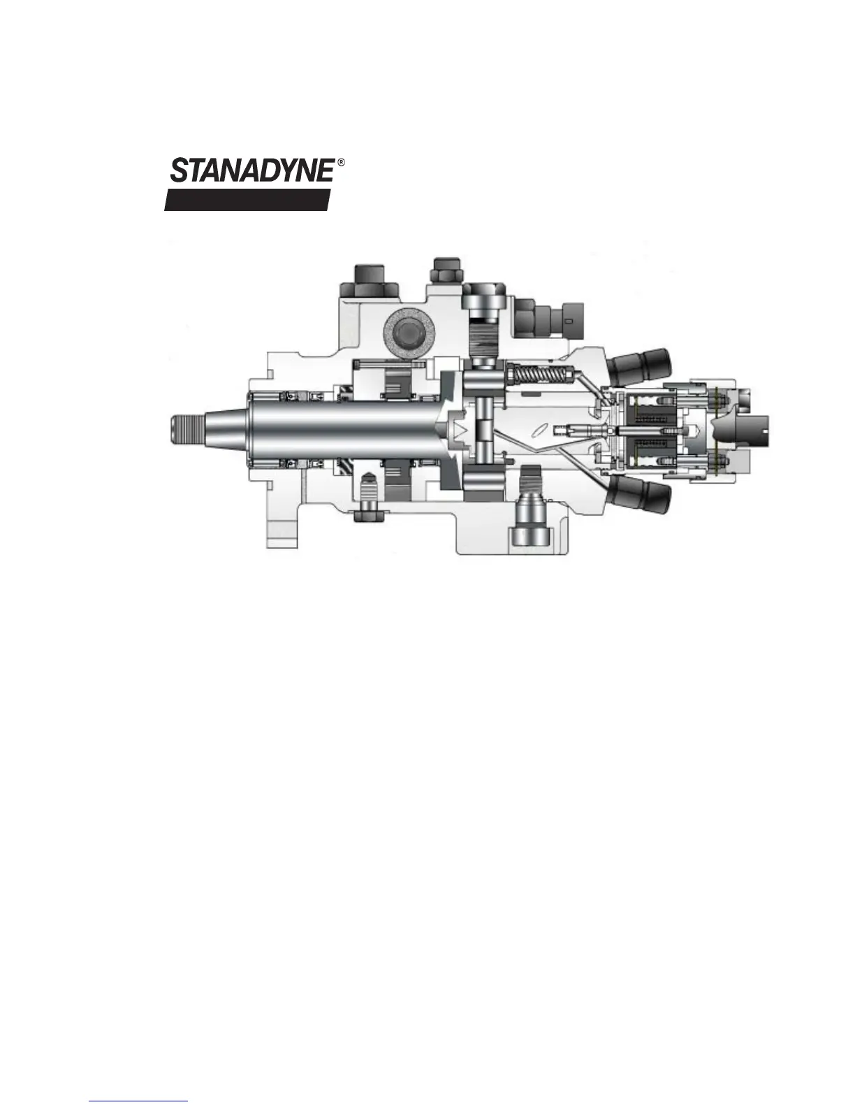
A. Components and Functions (Figure
1.1)
The main components of the DE pump are
pictured above in Figure 1.1. They include:
1. Fuel Inlet Fitting
2. Return Line Connector/Housing
Pressure Regulator
3. Heavy Duty Drive Shaft
4. Transfer Pump
5. Cam Ring
6. Distributor Rotor
7. Poppet Valve
8. Fuel Control Solenoid
9. Discharge Fittings with Snubber
Components
I
The main rotating components are the drive
shaft, the cam roller shoes and cam rollers,
transfer pump blades and their retainer, and the
distributor rotor and poppet valve.
In the DE pump Shown in Figure 1.1, the drive
shaft is supported at both ends by needle bear-
ings and carries the two cam roller shoes and
cam rollers. It also incorporates a slot, which
engages with a tang on the distributor rotor to
drive the latter. As the drive shaft is rotated, in-
ternal lobes on the cam ring drive the cam roll-
ers and shoes inward, simultaneously displac-
ing the two opposed pumping plungers carried
in the rotor. The number of cam lobes equals
the number of engine cylinders being served.
1.
2.
3 .
4.
5.
6.
7.
8.
9.
The distributor rotor in the 4-cylinder design of
the DE pump incorporates no charging ports
whereas the six cylinder design incorporates
one. Both designs incorporate one discharge
port. In the four-cylinder pump all charging fuel
must pass around the poppet valve that re-
Fig. 1.1
1