the transfer pump group, cam ring and head and
rotor assembly fit for erosion, wear or cracks.
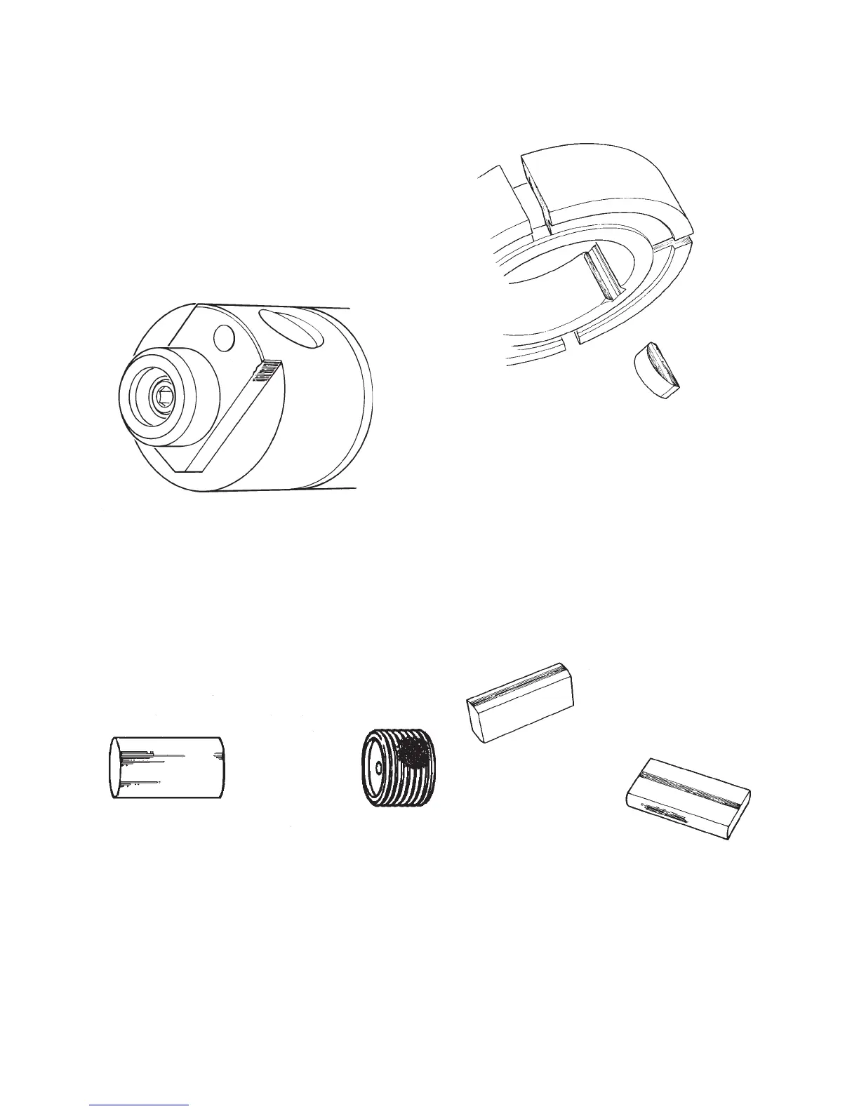
2. Distributor Rotor (Fig. 3.1) – Examine the
shank of the rotor for wear or erosion around
the discharge port area. Examine the poppet
valve seat for cracking or erosion. The drive
tang area may show polishing or wear in the
corners which contact the drive shaft as illus-
trated but this is considered normal.
3. Transfer Pump Regulator Piston and Ad-
justing Screw (Fig. 3.2) – Light scratches on
the regulating pistons are considered normal.
Examine the adjusting screw for adequate
thread retention compound and for tightness
of the orifice plate in the screw. Be sure that
the orifice is not plugged with foreign material.
4. Transfer Pump Blade Retainer and Drive
Key (Fig. 3.3) – Inspect the blade slots for scor-
ing, burring or excessive wear. Check to see if
oversize blades can be used. Examine the drive
key for damage and replace as necessary.
5. Transfer Pump Blades (Fig. 3.4) - Exam-
ine the blades for wear on the rounded ends
caused by contact with the liner or blade spring.
Also inspect the blades for wear caused by
contact with blade retainer. It is recommended
that used blades be reinstalled in the same ori-
entation that they were originally installed, that
is with the same surface contacting the liner.
Orientation of new blades is unimportant.
26
Fig. 3.1
Fig.3.2
Fig. 3.3
Fig. 3.4