6
screen where it acts on the end of the
regulating piston. The pressure over-
comes the spring force on the piston
and moves the piston in its bore un-
covering the regulating slot in the
sleeve. Fuel flowing through the regu-
lating slot joins the fuel entering the
pump and is recirculated. As pump
speed increases, transfer pump out-
put increases causing transfer pump
pressure to increase.
The transfer pump regulator plug as-
sembly (adjusting plug assembly)
provides a means of changing the
spring preload which adjusts trans-
fer pump pressure.
A sectionally thin, sharp edge orifice, lo-
cated in the transfer pump regulator plug
assembly provides the DE2 with a viscos-
ity compensation feature. Flow through this
orifice is unaffected by changes in viscos-
ity. With hot and/or low viscosity fuels, leak-
age past the regulating piston and bore
clearances increases causing fuel pressure
in the spring cavity to increase , since flow
through the orifice remains essentially the
same regardless of fuel viscosity. This in-
creased fuel pressure serves to assist the
regulator spring in resisting movement of
the piston, this uncovering less of the regu-
lator slot, when fuels are lower in viscosity.
This in turn causes an increase of transfer
pressure to offset the increased leakage
throughout the pump when fuel viscosity is
less then ideal.
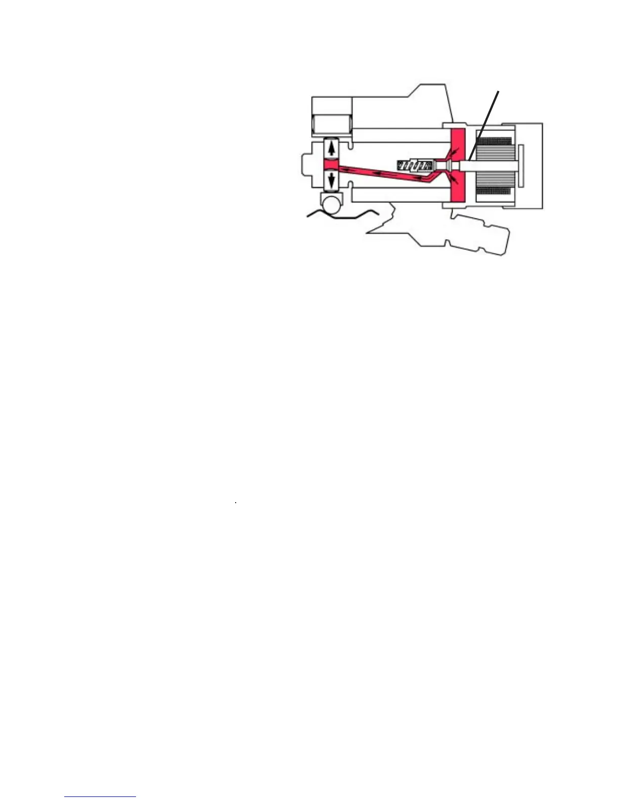
F. Charging (Figure 1.8, 1.9, 1.10 and
1.11)
As the drive shaft and rotor rotate, fuel un-
der transfer pump pressure flows out of the
transfer pump porting plate, through the
porting plate screw, down a passage in the
housing and into the head locking screw.
Cam
Roller
Armature Plate
Assy.
Fig. 1.8
From the head locking screw this fuel then
flows through two drillings in the hydraulic
head and fills the area around the poppet
valve and the fuel control solenoid arma-
ture. This fuel flows past the open poppet
valve, down through the rotor into the pump-
ing chamber filling the volume between the
two pumping plungers, which are then
forced outward.
On the six cylinder application, fuel from
the head locking screw is also directed to
a charging annulus in the hydraulic head
and feeds charging ports in the sleeve. As
the rotor revolves, an inlet passage in the
rotor registers with one of the charging
annulus ports allowing additional fuel to as-
sist in charging the plungers. With further
rotor rotation this charging port goes out
of registry within the hydraulic head trap-
ping the fuel charge in the pumping cham-
ber.
With the DE pump the pumping chamber
is filled completely between each injection
regardless of the quantity of fuel to be in-
jected into the engine. This differs greatly
from previous inlet metered D series
pumps where charging quantities were
metered based on the amount of metering
valve opening.
Power
Off
Valve
Open