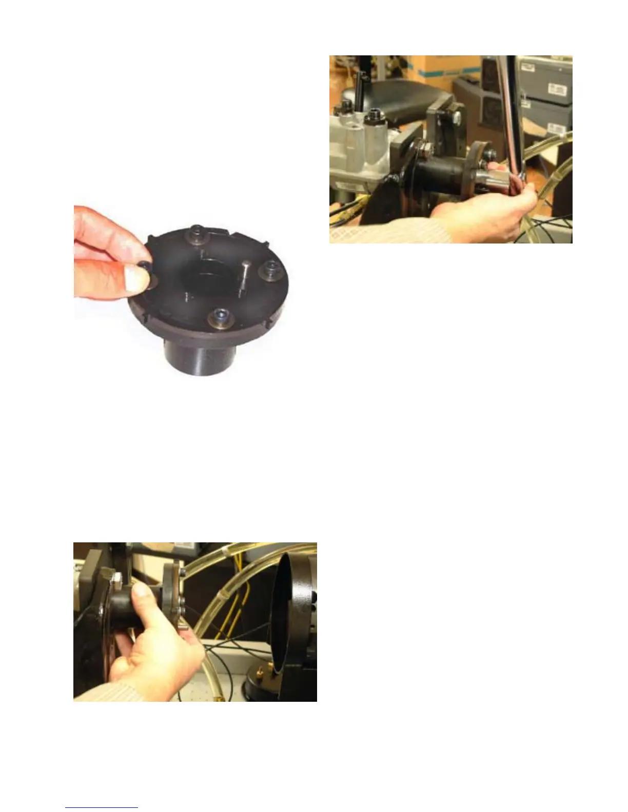
Step 3. Place the appropriate toothed wheel
on the Drive Adaptor. Note that these wheels
are marked “pump side” and “bench side”. The
“pump side” marking must be placed against
the drive adapter. (towards the pump when
the adapter is installed on the pump). Install
the four 8mm socket head cap screws and
washers finger tight. Ref. Figures 5.2 and 5.3.
Step 4. Install the drive adaptor assembly onto
the pump drive shaft. Install the washer and 24
mm nut onto the drive shaft finger tight Ref.
Figure 5.4.
Step 5. Mount the test bench mounting plate
and pump to the test bench pedestal per the
manufacturers recommended
procedure.Tighten the drive shaft retaining nut
to 140-150 ft-lbs. (190-200 N•m) with the tim-
ing pin installed (prevents the drive shaft from
rotating while tightening). Ref. Figure 5.5.
Step 6. Using a suitable 6.2/6.5L test bench
drive adaptor, align the pin and holes with the
DE pump drive adaptor. Install the mounting
bolts and tighten to the test bench manufac-
turers recommended torque value.
Step 7. Loosen the two upper flange bolts.
Remove the right side bolt (viewed from the
fuel control solenoid end), but leave the left
side bolt with a few threads of engagement.
NOTE: Due to the housing configuration, it
may be necessary to use a slightly shorter
mounting bolt in the left side flange hole.
Step 8. Assemble the 36263 Hall Effect
Bracket Assembly. Orientate the hall effect
sensor over the toothed wheel. With the
right side bracket mounting hole aligned with
right side pump flange mounting hole, insert
a pump mounting bolt and tighten finger
tight. Ref. Figure 5.6.
47
Fig. 5.3
Fig. 5.4
Fig. 5.5