Step 9. Rotate the Hall Effect Sensor Bracket
to engage the left side mounting bolt. Tighten
both flange mounting bolts according to the test
bench manufacturers procedures.
Step 10. Using the spring loaded timing spike
on the Hall effect sensor bracket, accurately
locate the correct rotational position of the
toothed wheel. Tighten the four 8 mm socket
screws to 20-30 lbf-in (2-3 N•m). Ref. Figure
5.7.
Step 11. Remove the timing pin and install the
36464 Housing Pressure tap. Connect the hous-
ing pressure gage supply line to the 36464
Housing Pressure Tap.
Step 12. Loosen the two positioning screws
on the top of the sensor bracket. Adjust the
Hall effect sensor, placing the center of the
sensor in line over the center of the toothed
wheel. Tighten the positioning screws to 20-30
lbf-in (2-3 N•m).
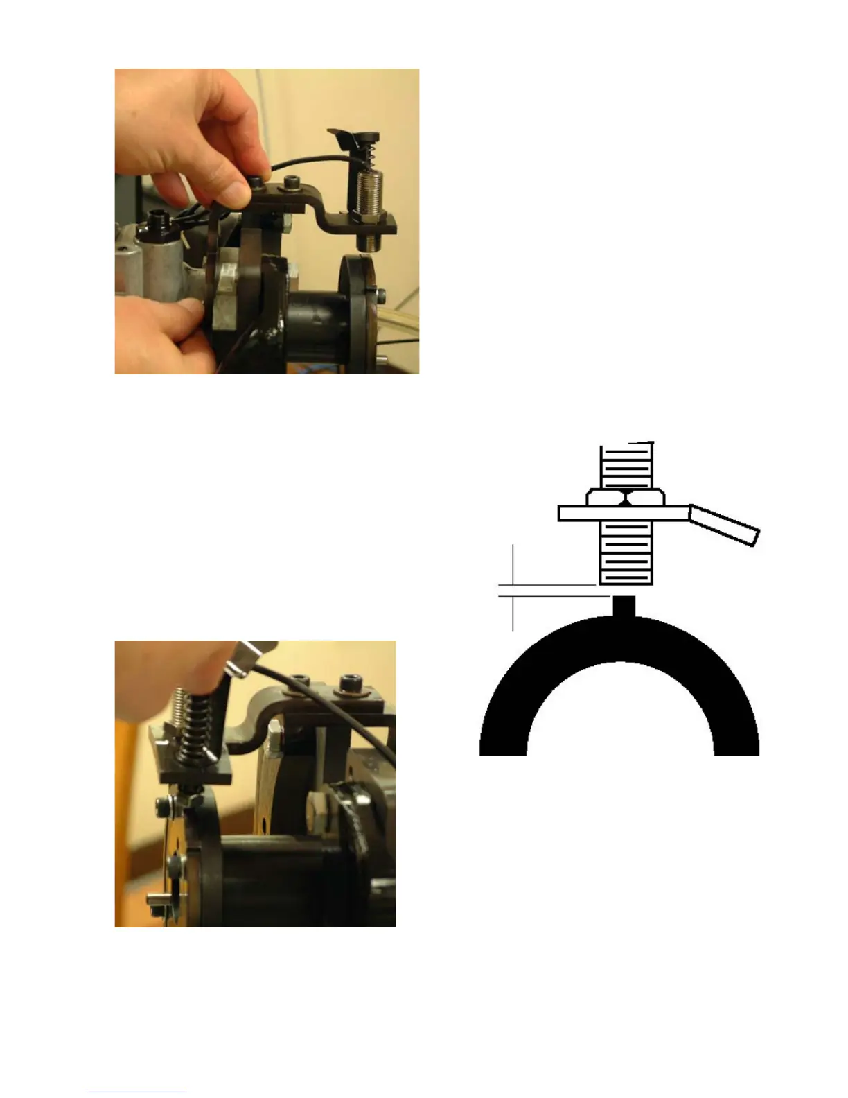
Step 13. Loosen the Hall effect sensor locknut
and adjust the sensor to achieve an air gap of
.100 inch (± .020 inch) {2.5 mm (±.40 mm)}
between the sensor and one of the teeth on
the toothed wheel. Hold the Hall effect sensor
while tightening the locknut to 20-30 lbf-in (2-3
N•m). Ref. Figure 5.8.
Step 14. Remove the plug in the head locking
screw and install the 33497 Transfer Pump
Pressure Tap. Connect the transfer pump pres-
sure gage line with a shut-off valve to the Trans-
fer Pump Pressure Tap.
Step 15. Install the 36274 Inlet and Return Fit-
ting Assembly on the pump. Tighten the tube
48
Fig. 5.7
Fig. 5.8
Fig. 5.6
2.5mm (± .4 mm)
.100 in. (±.020 in.)
Hall Effect
Sensor
Tooth Wheel