Pubn No: 30000H0K
9. REPAIR ...................................................................................................................31
9.1. REPLACING A FLASH DETECTOR PROBE.............................................................................31
9.2. REPLACING THE "O" RING SEAL............................................................................................31
9.3. REPLACING THE GAS CANISTER AND TUBING....................................................................32
9.4. REPLACING THE LID/SHUTTER ASSEMBLY..........................................................................33
10. SPECIFICATION...............................................................................................34
11. ACCESSORIES ................................................................................................35
12. SPARES ...........................................................................................................36
12.1. SPARES AVAILABLE.................................................................................................................36
12.2. SUGGESTED SPARES FOR 2 YEARS (2000 TESTS) .............................................................36
13. FREQUENTLY ASKED QUESTIONS ..............................................................37
APPENDIX A: SETA COOLANT MODULE 13870-0 .................................................39
APPENDIX B: SETA SOLIDS DISPENSER 13747-0 ................................................41
APPENDIX C: SETA COOLING BLOCK 13880-0.....................................................43
LIST OF FIGURES
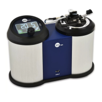
Figure 1 30000-0 Setaflash Series 3 Closed Cup Flash Point Tester ........................................................3
Figure 2 Main Component Parts .................................................................................................................7
Figure 3 Gas Canister and Related Components .....................................................................................10
Figure 4 Flash Detector Probe Replacement............................................................................................31
Figure 5 Sample Well 'O' Ring Seal Replacement....................................................................................32
Figure 6 Gas Canister Replacement.........................................................................................................32
Figure 7 Lid/Shutter Assembly Replacement............................................................................................33
Figure 8 30000-0 Wiring Schematic Diagram ...........................................................................................38
Issue K
10 Jun 2007
5