Pubn No: 30000H0K
3. INSTALLATION - GENERAL
WARNING: BEFORE INSTALLATION, REFER TO THE SAFETY NOTICES ON PAGE 2.
3.1. UNPACKING
The Setaflash Series 3 should be carefully unpacked upon receipt:
1) Retain all packaging for future storage or transport of the instrument.
2) Check the contents against the Packing List. The major items are:
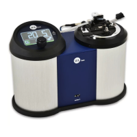
a) 30000-0 Series 3 Closed cup Flash Point Tester
b) 2ml syringe
c) Gas canister and igniter
d) Silicone rubber tubing for gas canister to gas jet connection
e) Silicone Sample Well ‘O’ Ring Seal for cup/lid (red coloured)
f) Viton Sample Well ‘O’ Ring Seal for cup/lid (black coloured)
g) Mains power cable
h) Automatic flash detector probe
i) Series 3 Manuals (on CD)
j) Quick Start Guide.
3) Check the Setaflash Series 3 visually for damage, particularly if the packaging is damaged in any
way.
4) Where applicable, verify that the operating voltage and frequency marked on the instrument match
the local power supply.
5) Any damage, shortfall, or problems with compatibility to local power supply must be notified to
Stanhope-Seta or their agents at the earliest opportunity.
Note: Each unit is tested for electrical safety is then calibrated. A number of Flash Point tests to
verify operation are carried out before despatch. This may result in some discolouration
of the sample cup and surrounding area.
3.2. LOCATION
1) The Setaflash Series 3 should be used in an area of the laboratory that has a stable day to day
temperature.
2) The area must have adequate ventilation and fume extraction.
3.3. POWER SUPPLY CONNECTIONS
3.3.1. MAINS SUPPLY OPERATION
1) Setaflash Series 3 can be operated from either a 115Vac or 220Vac mains supply.
2) Verify that the voltage and frequency shown on the identification plate suit the local power supply,
and set both the voltage selectors appropriately.
3) Connect the power supply lead to the supply using the following colour convention :-
BROWN - LINE/LIVE
BLUE - NEUTRAL
GREEN/YELLOW - EARTH/GROUND
Issue K
10 Jun 2007
9