3. HDV System Components
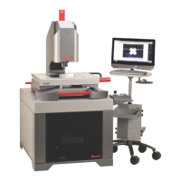
3.1 Manual System Components
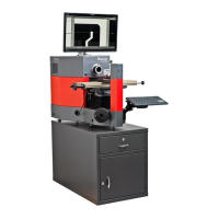
Figure 1. System component overview, manual system
3.2 Manual Position and Focus Controls
Precision X-axis positioning is by rotating a knurled hand wheel with a hand crank, as shown in
Figures 1 and 2. The stage can be disengaged from the shaft of the hand wheel by raising the
lever of a latch block around the shaft, thereby allowing the stage to be pushed directly by hand
for coarse X-axis positioning. The stage is reengaged to the shaft by lowering the lever of the
latch block.
Y-axis positioning is via the large hand crank at the base of the unit, as shown in Figures 1 and 2.
Rotate clockwise to raise the stage, counterclockwise to lower the stage.
The stage can be rotated by ±15° around a vertical axis to provide skew adjustment for parts
that are not perfectly aligned with the stage. The skew angle can be read to a precision of 10’
by means of a Vernier scale. To release the stage for skew adjustment, first release the locking
levers at the right and left of the rotation mechanism that supports the stage. Turn the levers
LED surface
illumination
Video camera
lens
LED profile
illumination
Hand crank
for X-axis
(left-right)
Protractor for
±15° skew
measurement
Keyboard
on swing-
out arm
Hand crank
for Y-axis
(vertical)
Steel pedestal
(optional)
24” touch-screen
monitor
System On-Off
switch
Two external
USB ports
Manual X-Y
stage
Right clamp for
skew angle
Comparator
housing for
computer and
M3 controller
Leveling feet