Tech Support: www.steppir.com/support Tel: 425.891.6134 support@steppir.com
Page 28
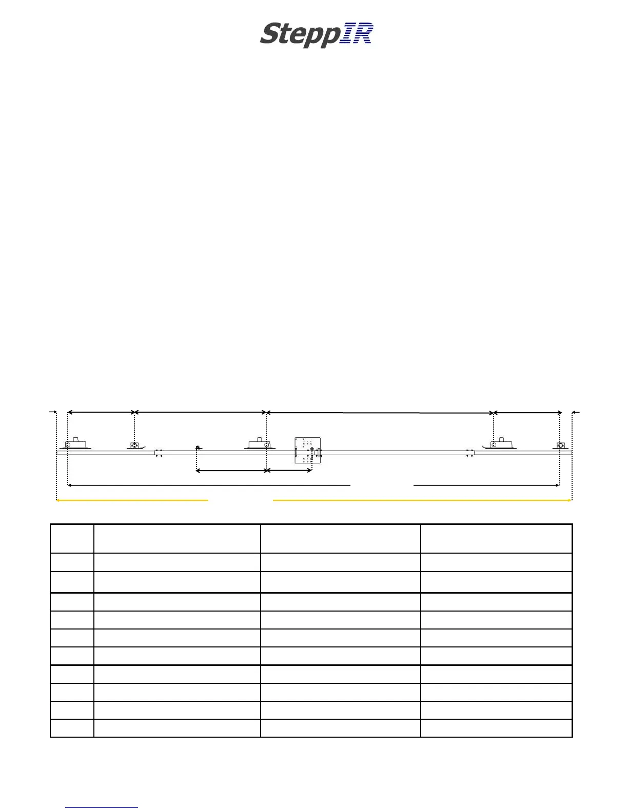
H
K (232.0 in)
KEY Start measurement at
center-point of:
Finish measurement at
center-point of:
Measurement distance be-
tween points
A Boom edge* Director EHU 05.00 inches
B Director EHU Loop return 30.00 inches
C Loop return Driven EHU 59.50 inches
D Driven EHU Reflector EHU 102.50 inches
E Reflector EHU Loop return 30.00 inches
F Loop return Boom edge* 05.00 inches
G 6m passive (optional) Driven EHU 31.00 inches
H Driven EHU EZ-Eye Eyebolt 20.50 inches
J Director EHU Reflector EHU 222.00 inches
K Boom edge* Boom edge* 232.00 inches
* There is no center-point measurement at the boom edge—place the ruler literally on the edge of the boom
A
5.0
in
F
5.0
in
B (30.0 in)
C (59.5 in)
D (102.5 in)
E (30.0 in)
G (31.0 in)
20.5 in
J (222.0 in)
CHAPTER THREE
SECTION 3.0
MOUNTING THE EHU’S ON THE BOOM (continued)
EHU CENTER-TO-CENTER SPACING MEASUREMENTS
It is critically important that the center-to-center spacing is correct when assembling your SteppIR Ya-
gi. Use figure 3.02 for placement of each of the elements. Start from the left edge of the boom and
measure from there.
As you assemble each of the element housing units (EHU’s), refer to this drawing. We recommend
this sequence:
1. Secure the element mounting plates to the boom using the correct saddles and fasteners (be sure
to use anti-seize on all stainless steel fasteners). Tighten enough to hold them in place, but loose
enough so you can move the mounting plates for final tightening.
2. Wire the EHU’s and secure them to the element mounting plates (don’t forget the gasket!). The
mounting plate itself acts as the lid for the DB18 EHU’s.
3. Measure your center-to-center lengths, level the mounting plates and firmly tighten.
4. Re-measure all of your lengths and correct if needed. Take your time, get it right.
All of this is covered in greater detail in this manual, but it’s important to understand the proper flow
BEFORE you start—it will save a lot of time.
FIG. 3.02