Tech Support: www.steppir.com/support Tel: 425.891.6134 support@steppir.com
Page 63
CHAPTER EIGHT
SECTON 8.0
OPTIONAL 40/30 LOOP TRUSS KIT
INSTALLING THE TRUSS SUPPORT MAST
The great advantage of telescoping fiberglass poles are that they are both flexible and extremely strong. This
is a significant advantage for such adverse weather situations as high winds, icing or snow accumulation. The
only negative to this, is because of the flexibility, there is a slight natural “droop” at the element ends. This
droop has no impact whatsoever on performance, but some people do not care for the look. On the DB18 Ya-
gi, it is more pronounced because the center, Driven element is a straight telescoping pole, which droops less
than the 40/30 loop elements on either side of it. For aesthetics reasons only, we offer the optional 40/30 loop
end truss kit, which allows for the leveling of the Director and Reflector loop elements to the same latitude as
the single straight Driven element. This makes for a better overall profile for the Yagi. These trusses do not
have any impact on load bearing.
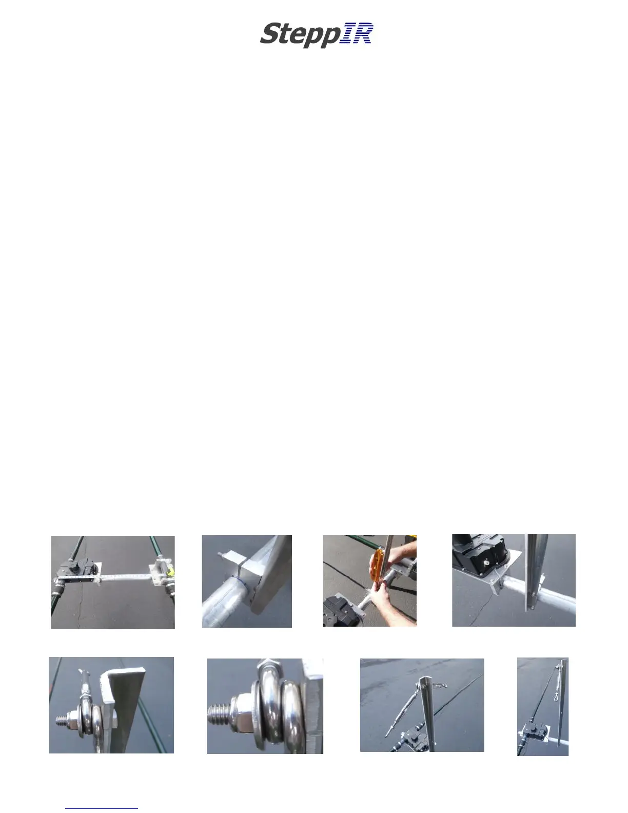
The truss mast needs to be mounted so that it is centered on the halfway point between the EHU center-point
and the return tube center-point. The overall length between the two center-points is 30 inches, so the half-
way point is 15 inches. Make a mark on the boom 15 inches between the two center-points as shown in figure
8.01.
Locate the truss support (PN 10-1054-01) and two 1-3/4” aluminum saddle halves (PN 10-1601-03). Place the
saddles so that the edge of the saddle is on the edge of the mark as shown in figure 8.02. This will ensure
that the support is indeed on the centerpoint. Insert two of the 5/16” x 3-/12” hex head bolts (PN 60-0065)
and secure with 5/16” Nylock nuts (PN 60-0046). Remember to use anti-seize on the stainless steel fasteners.
Level the support before tightening as shown in figure 8.03. The orientation between the saddle and the Direc-
tor element is shown in figure 8.04.
Attach each of the 4 inch stainless steel turnbuckles (PN 60-0083) using the 1/4” x 1-1/4” hex head bolt (PN
60-0110), two of the 5/16” stainless steel flat washers (PN 60-0033) and 1/4” Nylock nuts (PN 60-0030) as
shown in figure 8.05. The stainless steel washers are both positioned between the eye of the outside turn-
buckle and the Nylock nut as shown in figure 8.06.
Figure 8.07 shows the completed truss support assembly and figure 8.08 shows the orientation of the truss
support to the boom.
FIG. 8.01
FIG. 8.02
FIG. 8.04 FIG. 8.03
FIG. 8.05
FIG. 8.06
FIG. 8.07
FIG. 8.08