Tech Support: www.steppir.com/support Tel: 425.891.6134 support@steppir.com
Page 71
CHAPTER TEN
SECTION 10.1
INSTALLING THE OPTIONAL BOOM TRUSS (continued)
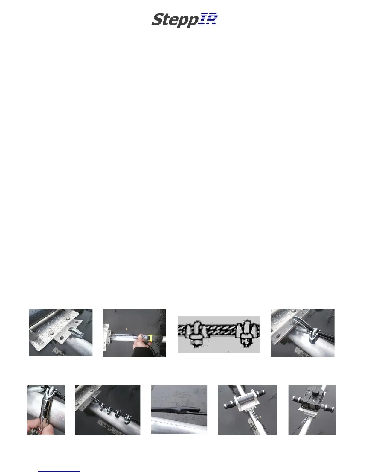
PHILLYSTRAN TRUSS INSTALLATION
When securing the Phillystran truss cable, the rule of “don't saddle a dead horse” applies. You must be cer-
tain that the saddle portion of the wire clip is on the longer or “live” side of the Phillystran, and the U-bolt
section is on the “dead” or (short) side of the Phillystran. Because of this, how you thread the Phillystran
through the thimble is important. The lengths of the Phillystran are different on each side of the truss. The
Director side of the truss uses approximately 85 inches of Phillystran to make up the truss, and the Reflector
side uses approximately 100 inches of Phillystran. It is best to “trim as you go”, that way you can minimize
the opportunity for error.
When preparing the Phillystran truss, you will need to bring the Phillystran from below the thimble so that
the “dead” side is facing towards the sky. Insert the 3/16” thimble (PN 60-0048) into the middle hole on
the truss attachment plate as shown in figure 10.12. Loop the Phillystran around the thimble until approxi-
mately 8” of the Phillystran is on the “dead” side as shown in figure 10.13.
Figure 10.14 shows how to position the two pieces of Phillystran cable into the wire clip saddle. Position the
first of the four wire clips (PN 60-0045) so that the wire clip is as close to the thimble as possible, as shown
in figure 10.15. Tighten the wire clip, alternating between each nut so that the tightening force is evenly
distributed. Hold each portion of the Phillystran in place while tightening, to ensure that a good mate is
formed between the two cables. Wait 20 minutes and tighten some more, as cold-flow of the plastic usually
occurs. A great way to do the initial tightening is to use a 7/16” deep socket and hand turn, as shown in
figure 10.16. This allows you to get pretty tight and in good position on the two cables before doing the
final tightening. Position the next wire clip approximately 1 inch behind the first wire clip and tighten ac-
cordingly. Repeat with the remainder of the wire clips as shown in figure 10.17.
Locate the plastic end cap (PN 60-0044) and push it onto the end of the Phillystran as shown in figure 10.18.
Secure the Phillystran pieces and the cap at the end of the wire clips with electrical tape.
Figure 10.19 shows the completed truss end for the Director return tube side. Repeat for the Reflector
element. Figure 10.20 shows the completed truss end on the Reflector side.
FIG. 10.15
FIG. 10.12
FIG. 10.13
FIG. 10.14
FIG. 10.17
FIG. 10.18
FIG. 10.19
FIG. 10.20
FIG. 10.16