Tech Support: www.steppir.com/support Tel: 425.891.6134 support@steppir.com
Page 70
CHAPTER TEN
SECTION 10.1
INSTALLING THE OPTIONAL TRUSS (continued)
PHILLYSTRAN TRUSS INSTALLATION
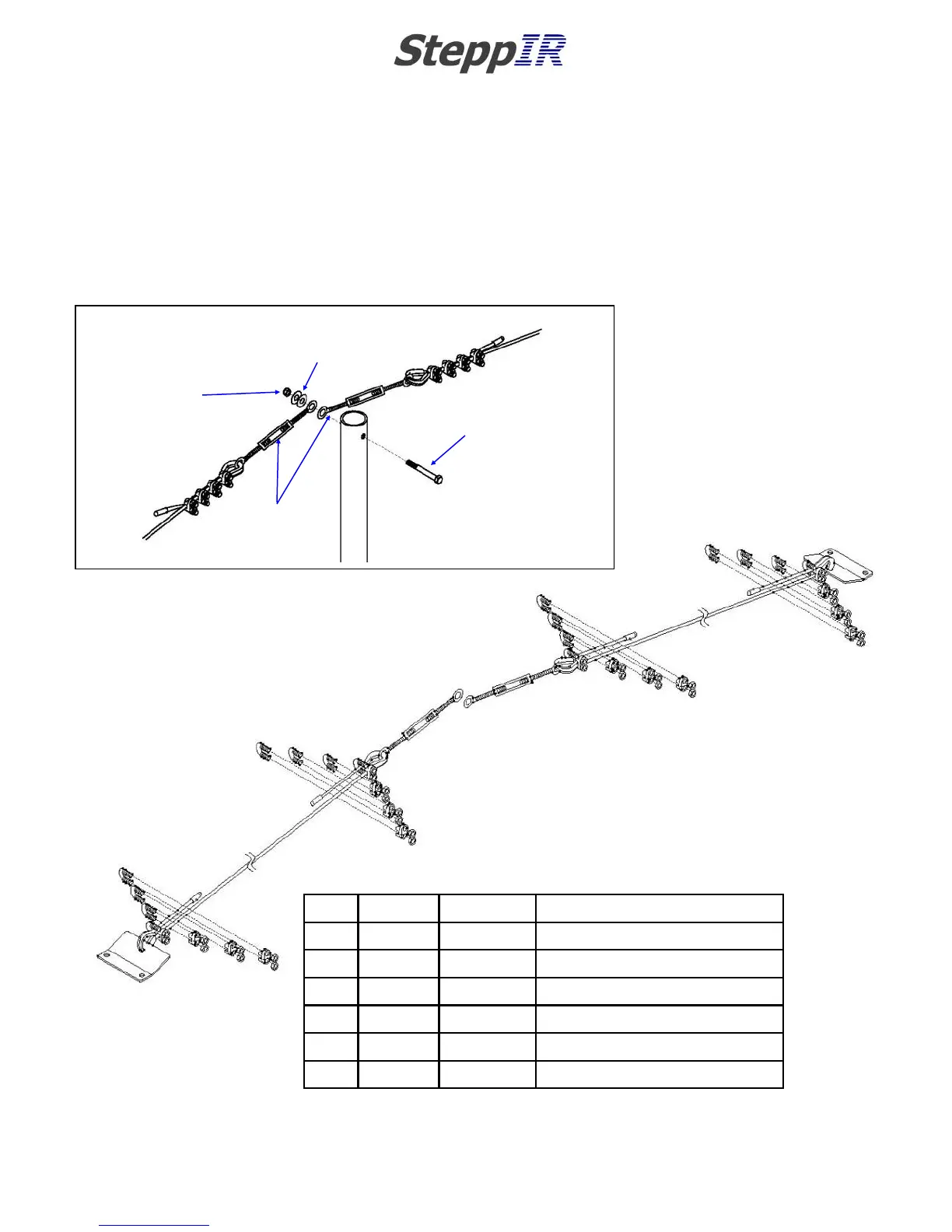
The following explosion drawing for the Phillystran truss will come in handy while working through the
next section. Figure 10.10 shows the detail at the top of the truss support mast. Insert the 5/16” x 2-
3/4” hex head bolt (PN 60-0107) through the boom truss mast. Position each 4 inch turnbuckle (PN 60-
0083) over the bolt. Place two 5/16” flat washers against the outside turnbuckle. Attach the 5/16” Ny-
lock nuts (PN 60-0046). Figure 10.11 shows the Phillystran layout with appropriate fasteners.
A
A
A
A
A
A
A
A
A
A
A
A
A
A
A
A
B
B
F
F
F
F
C
C
D
D
H
E
D
D
Key QTY Part # Description
A 16 60-0045 3/16” Wire rope clip
B 2 10-1607-01 Truss attachment plate
C 2 60-0083 4” Stainless turnbuckle
D 4 60-0044 Phillystran end cap
E 16 FT 21-8002 Phillystran 1200I (trim as you go)
F 4 60-0048 3/16” Wire thimble
Order of assembly
(closest first)
1
3
2
4
QTY 1: 5/16” x 2-3/4”
Hex head bolt
PN 60-0107
QTY 2:
5/16” Flat washer
PN 60-0033
QTY 1:
5/16” Nylock nut
PN 60-0046
QTY 2:
60-0083
4” Turnbuckle
FIG. 10.10
FIG. 10.11