Tech Support: www.steppir.com/support Tel: 425.891.6134 support@steppir.com
Page 69
Key QTY Part # Description
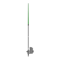
A 1 10-1618-11 30” Boom truss support mast
B 4 60-0115 5/16” x 4-1/2” Hex head bolt
C 4 10-1601-22 1-3/4” Aluminum saddle half
D 4 10-1613-01 1” aluminum spacer
E 4 60-0046 5/16” Nylock nut
A
B
B
B
B
C
C
C
C
D
D
D
D
E
E
E
E
CHAPER TEN
SECTION 10.0
INSTALLING THE OPTIONAL BOOM TRUSS
INSTALLING THE BOOM TRUSS SUPPORT
The DB18 Yagi has a sturdy boom that is engineered to survive tough weather conditions without the need for
a boom truss. However, for people in extreme areas of the world where ice and snow loading occur on a regu-
lar basis, the optional boom truss is a great way to go.
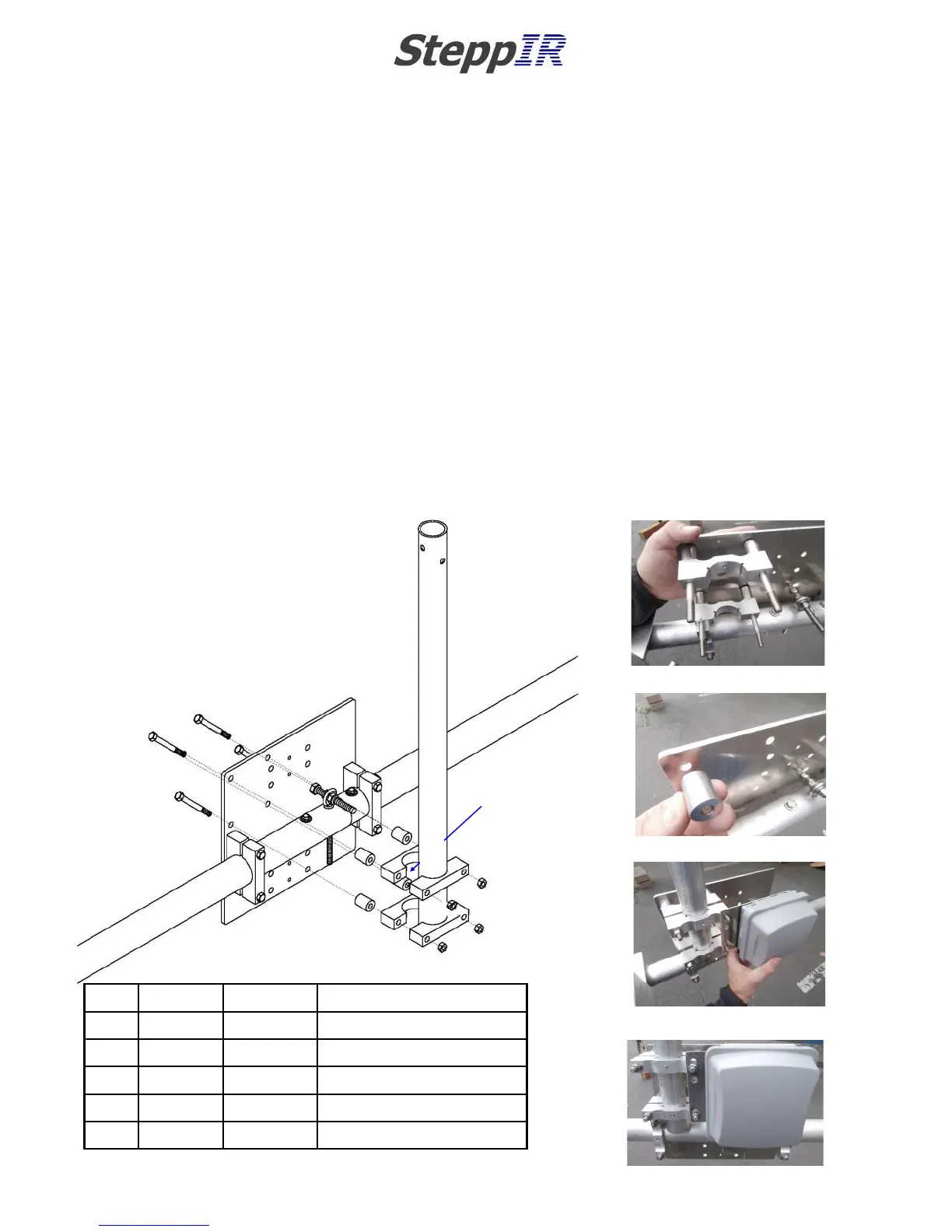
Review figure 10.01. Insert four of the 5/16” x 4-1/2” hex head bolts (PN 60-0115) so the threads of the bolts
are on the boom side of the mast plate. Insert the 1” aluminum spacers (PN 10-1613-01) onto the hex head
bolts, followed by the first half of the 1-3/4” aluminum saddle (PN 10-1601-22) as shown in figure 10.02. Fig-
ure 10.03 shows the orientation of the spacers. Position the truss support mast so that it is resting on the alu-
minum saddle, then slide the other half of the saddle onto the hex head bolts as shown in figure 10.04.
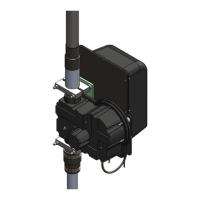
When the boom truss option is purchased, the location of the connector junction box needs to be changed.
Install the connector junction box on the saddles so that the lid of the junction box opens from the bottom, and
the orientation matches that of figure 10.04. Holding the connector junction box in place, insert the 5/16” Ny-
lock nuts (PN 60-0046) onto the hex head bolts and tighten, but leave loose enough so you can align the truss
support mast in the next step. Figure 10.05 shows the completed truss support mast assembly.
FIG. 10.01
FIG. 10.03
FIG. 10.04
FIG. 10.02
FIG. 10.05


 To Next Page