Tech Support: www.steppir.com/support Tel: 425.891.6134 support@steppir.com
Page 68
Locate the 6m mounting plate (PN 10-1019-31). Using the 1 inch U-bolts (PN 60-0001) as shown in figure
9.11, place the 6m passive element on top of the 6m mounting plate with the slit in the plastic sleeve point-
ing downward. Position the plastic insulator so that it is centered between the two U-bolts. Tighten using
the 1/4” Nylock nuts (PN 60-0030). Be careful not to over-tighten or you will crack the plastic insulator.
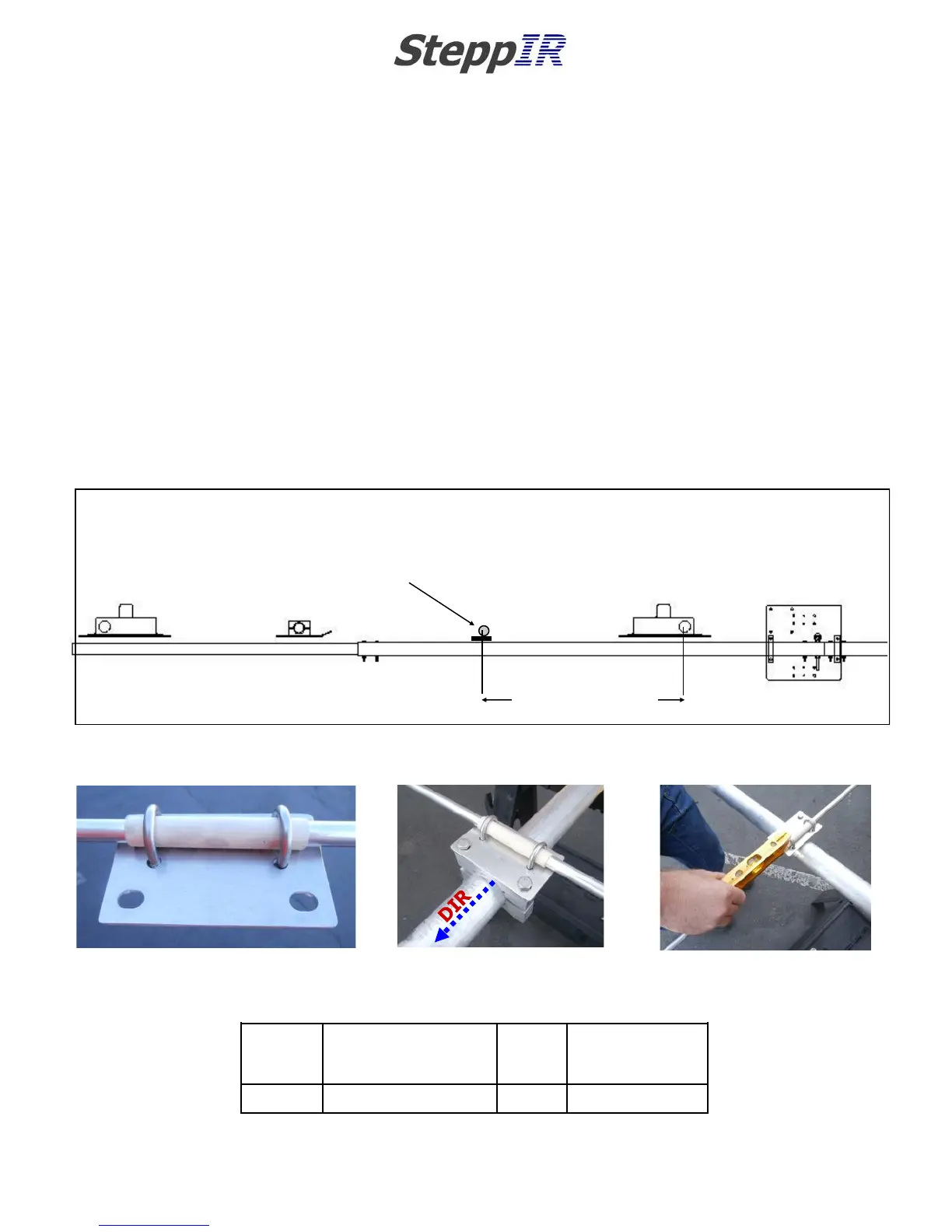
Figure 9.10 shows the center-to-center spacing of the 6m passive element. Position two 2” aluminum sad-
dle halves (PN 10-1601-22) on the boom and insert two 5/16” x 3-1/2” hex head bolts (PN 60-0065). At-
tach the 6m mounting plate with the bolt holes for the aluminum saddles facing towards the director ele-
ment as shown in figure 9.12. Secure with 5/16” Nylock nuts (PN 60-0046) but leave loose enough for lev-
eling of the element. Figure 9.14 shows pertinent data for this step.
Place a level on the 6m passive element as shown in figure 9.13. When the position is correct, tighten the
aluminum saddles. Be sure to use anti-seize on the stainless steel fasteners.
CHAPER NINE
SECTION 9.1
OPTIONAL 6M PASSIVE ELEMENT KIT (continued)
MOUNTING THE PASSIVE ELEMENT TO THE BOOM
FIG. 9.11
FIG. 9.12
FIG. 9.13
6m
Passive
element
Center-to-center
measurement Driven
EHU to 6m passive
Saddle
Size
Hex head
bolt length
D1A 31 inches / 78.7 cm 2 inch 5/16” x 3.-1/2”
FIG. 9.14
70-3401-01
20m Driven
70-3406-01
40m Director
6M PASSIVE
ELEMENT D1A
31” (78.7 cm)
FIG. 9.10