Tech Support: www.steppir.com/support Tel: 425.891.6134 support@steppir.com
Page 65
CHAPER EIGHT
SECTION 8.2
OPTIONAL 40/30 LOOP TRUSS KIT (continued)
ROUTING THE DACRON TRUSS CORD
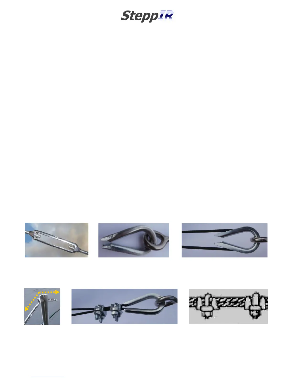
Before inserting the rope through the eyebolt of the 4” turnbuckle, unthread each eye so that there is
approximately 3/8” thread remaining in the frame of the turnbuckle portion, as shown in figure 8.20.
Locate the 1/8” thimble (PN 60-0158). Spread the thimble apart enough to slide on to the eye of the
turnbuckle. When the thimble is through the eyebolt, bend the tips of the thimble back as close to each
other as possible, as shown in figure 8.21.
Thread the Dacron truss cord through the eye of the turnbuckle and around the 1/8” thimble as shown
in figure 8.22. Pull the truss cord back down to the truss coupler on the opposite side of the loop. In-
sert the Dacron cord through the truss coupler (refer to prior page for instructions), pulling the cord
tight so that there is no slack on either side of the cord. The procedure for securing the Dacron truss
cord on this end of the loop is exactly the same as the truss coupler you prepared initially.
At this point of the installation of the 40/30 loop element, it is important to assemble the truss couplers
and Dacron truss cord on the other side of the EHU. Because of the significant torque generated by
leveling of the elements, there needs to be equal force applied on each side as shown in figure 8.23.
When the 40/30 loops on each side of EHU have both been prepared, attach two 1/8” galvanized wire
clips (PN 60-0157) on each side as shown in figure 8.24. Position the first wire clip as close as possible
to the tip of the thimble. Position the second wire clip an inch behind the first. Be certain that the
rope is “stacked” one on top of the other as shown in figure 8.25. Tighten the wire clips firmly.
FIG. 8.25
FIG. 8.20
FIG. 8.21
FIG. 8.22
FIG. 8.23
FIG. 8.24