Tech Support: www.steppir.com/support Tel: 425.891.6134 support@steppir.com
Page 42
CHAPTER FOUR
SECTION 4.2
COAX SWITCH HOUSING (continued)
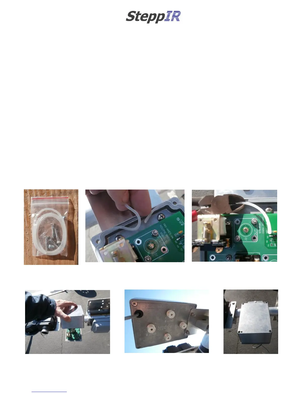
SEALING & SECURING THE COAX SWITCH HOUSING
Locate the small plastic baggie that contains the enclosure gasket and the screws used for securing it
as shown in figure 4.20. Inside this baggie there will also be two tiny 1/4” screws—these will not be
used.
The gasket is more accurately described as “piping” material. Push this material into the gasket tray as
shown in figure 4.21. There is plenty of material, and you will need to trim it as shown in figure 4.22.
Lower the top half of the enclosure and position so that the flathead threaded screws included in the
baggie are lined up with the holes as shown in figure 4.23. The screws will be inserted from the bot-
tom of the housing as shown in figure 4.24. Tighten so that the lid is firmly in place.
You will likely need to take the lid off for the final wiring test, but leaving it in place is necessary in or-
der to protect the components of the coax switch housing while completing assembly of the antenna.
Figure 4.25 shows the completed coax switch housing.
FIG. 4.20
FIG. 4.21
FIG. 4.22
FIG. 4.23
FIG. 4.25
FIG. 4.24