Tech Support: www.steppir.com/support Tel: 425.891.6134 support@steppir.com
Page 72
CHAPTER TEN
SECTION 10.1
INSTALLING THE OPTIONAL BOOM TRUSS (continued)
PHILLYSTRAN TRUSS INSTALLATION (continued)
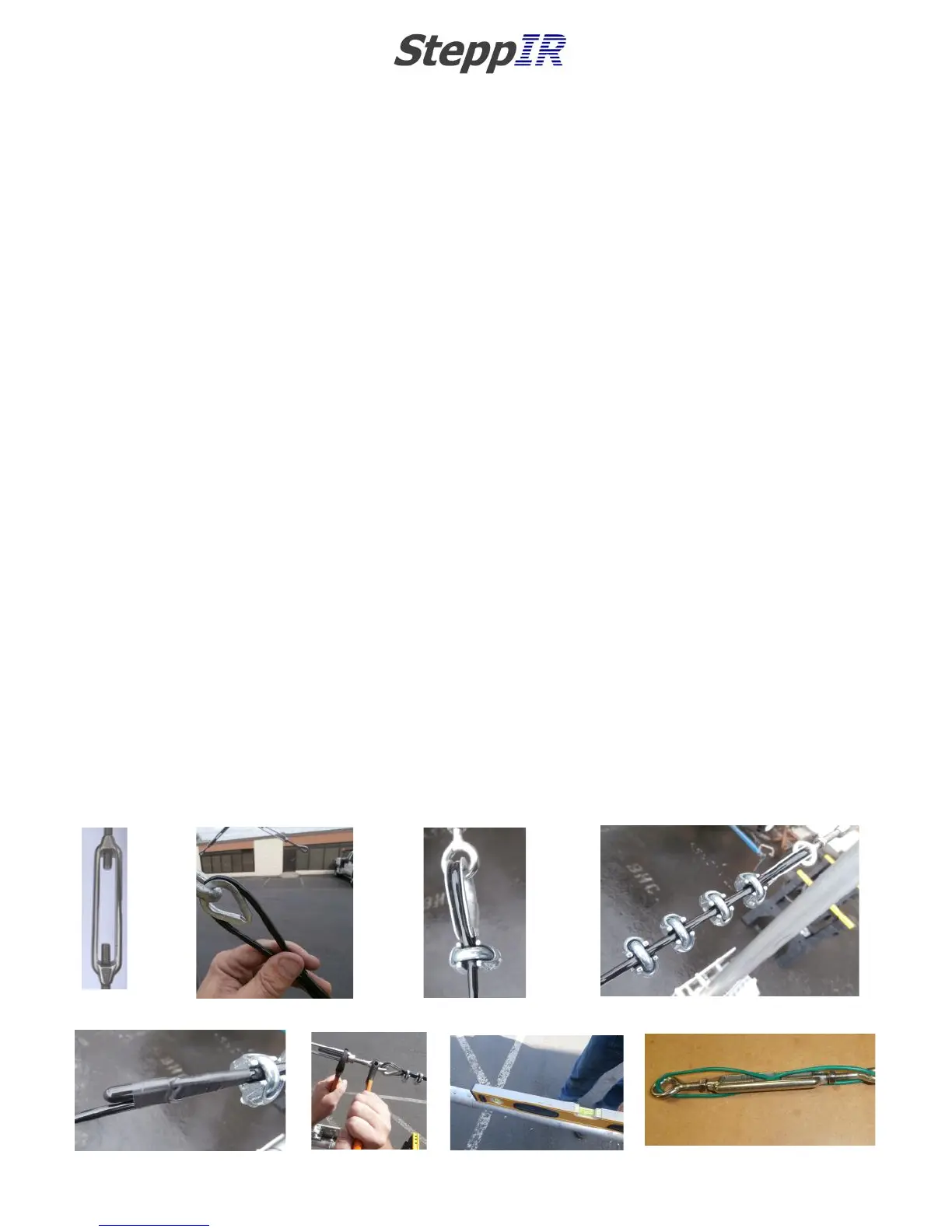
When attaching the Phillystran truss material to the turnbuckle located on the truss support mast, the rule
of “don't saddle a dead horse” still applies. You must be certain that the saddle portion of the wire clip is on
the longer or “live” side of the Phillystran, and the U-bolt section is on the “dead” or (short) side of the Phil-
lystran. Locate the 3/16” galvanized thimbles (PN 60-0048) and pry the end apart so that it will slide over
the eye portion of the turnbuckle. When the thimble is attached, be sure to bend the ends back so that it
cannot fall off. Unwind the turnbuckle so that approximately 3/8 inch of threads are still inside the frame,
as shown in figure 10.21. The slack is needed so that you can appropriately tighten the Phillystran once
secured to the turnbuckle.
When preparing the Phillystran truss, you will need to bring the Phillystran from below the thimble as you
did on the other end of the truss. Loop the Phillystran around the thimble until the Phillystran is as tight as
possible. Leave approximately 8” of the Phillystran on the “dead” side as shown in figure 10.22 and trim
with a utility knife.
While holding the Phillystran so that it remains tight, position the first of the four wire clips (PN 60-0045) so
that the wire clip is as close to the thimble as possible as shown in figure 10.23. Tighten the wire clips, al-
ternating between each nut so that the tightening force is evenly distributed. Hold each portion of the Phil-
lystran in place while tightening, to ensure that a good mate is formed between the two cables. Wait 20
minutes and tighten some more, as cold-flow of the plastic usually occurs. Position the next wire clip ap-
proximately 1 inch behind the first wire clip and tighten accordingly. Repeat with the remainder of the wire
clips as shown in figure 10.24.
Locate the plastic end cap (PN 60-0044) and push it onto the end of the Phillystran as shown in figure
10.25. Secure the Phillystran pieces at the end of the wire clips with electrical tape.
Repeat for the other side of the boom. When both sides are finished, use two adjustable wrenches, one to
hold the eye stationary and the other to turn the frame of the eyebolt as shown in figure 10.26. Place a
level on the boom as shown in figure 10.27. When the boom is level, tighten the nuts on each end of the
frame of the eyebolt so that the eyebolt cannot adjust accidentally once the antenna is in the air. As a sec-
ondary measure, weaving wire through the eyebolts and the frame can also prevent the eyebolts from loos-
ening, as shown in figure 10.28.
FIG. 10.21
FIG. 10.23
FIG. 10.24
FIG. 10.25
FIG. 10.26
FIG. 10.22
FIG. 10.27
FIG. 10.28