Tech Support: www.steppir.com/support Tel: 425.891.6134 support@steppir.com
Page 37
CHAPTER THREE
SECTION 3.5
MOUNTING THE EHU’S ON THE BOOM (continued)
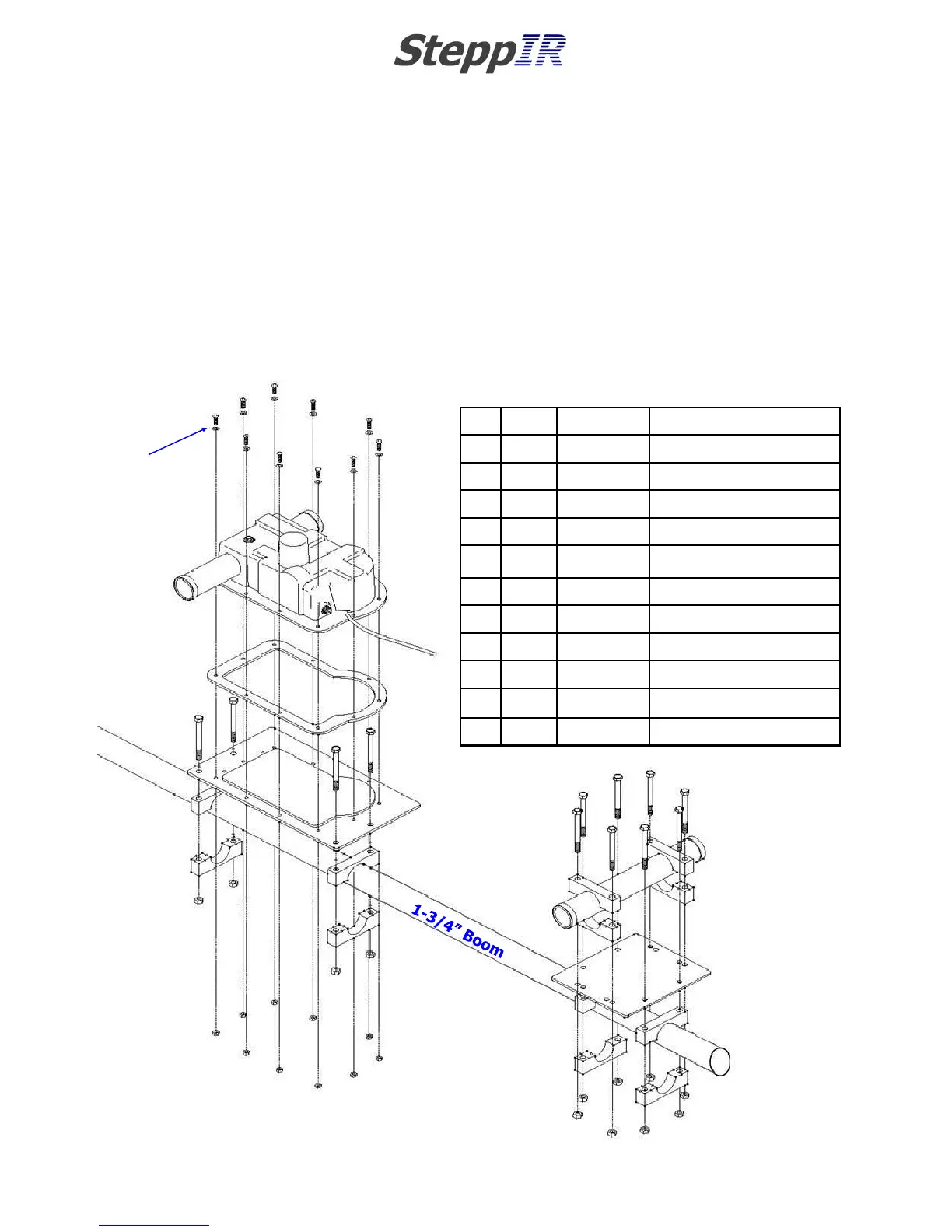
REFLECTOR EHU & RETURN TUBE ASSEMBLY DRAWING
The parts explosion drawing in figure 3.50 gives you an overview of the assembly of the reflector EHU.
Detailed instructions follow.
NOTE: If you have purchased the optional boom truss, be sure to refer to Chapter Ten before assem-
bling and mounting the Director and Reflector EHU’s. Even though the installation of the boom truss
does not take place until the DB18 Yagi is nearly completed, there are two truss attachment plates (PN
10-1607-01) that need to be installed while working in Chapter Three.
Key QTY Part # Description
A 10 60-0017 #10x 3/4” Machine screw
B 10 60-0018 #10 Flat washer
C 10 60-0019 #10 Nylock nut
D 12 60-0065 5/16”x3-1/2” Hex head bolt
E 12 60-0046 5/16” Nylock nut
F 1 70-3403-01 Driven Element EHU
G 1 10-1502-01 Element housing gasket
H 1 10-1015-11 Element mounting plate
J 12 10-1601-03 1-3/4” Aluminum saddle half
K 1 10-1608-01 Element return plate
L 1 10-1015-11 EST Return tube
A (x10)
B (x10)
C (x10)
E (x8)
D (x8)
G
H
J
J
J
J
J
J
J
J
J
J
J
K
L
J
E
E
E
E
F
D
D
D
D
FIG. 3.50